Welcome back to the world of random. In this article we’ll be focusing on modern designers who took the early concepts of randomness and ran with them in new directions. From esoteric noise boxes that seem to have a mind of their own to cleverly crafted software implementations of randomness, we’ll explore some of the more modern ways random has been reinvented.
Grant Richter's Random Part 1: Wogglebug
The Wogglebug is a synthesizer module designed by Grant Richter of Wiard synthesizers. Originally created for his Wiard 6U format, the Wogglebug is his reimagining of the Buchla 265, discussed in the previous random article, but is a whole new beast. The Wogglebug uses a pair of phase locked loop (PLL) ICs to create its unique and characteristic slewing effects and random voltage generation. The Wogglebug has three distinct sections: a clock section, a random voltage section, and an audio section. The clock section has a voltage controllable clock circuit and a clock output. It also includes a clock input for externally clocking the module.
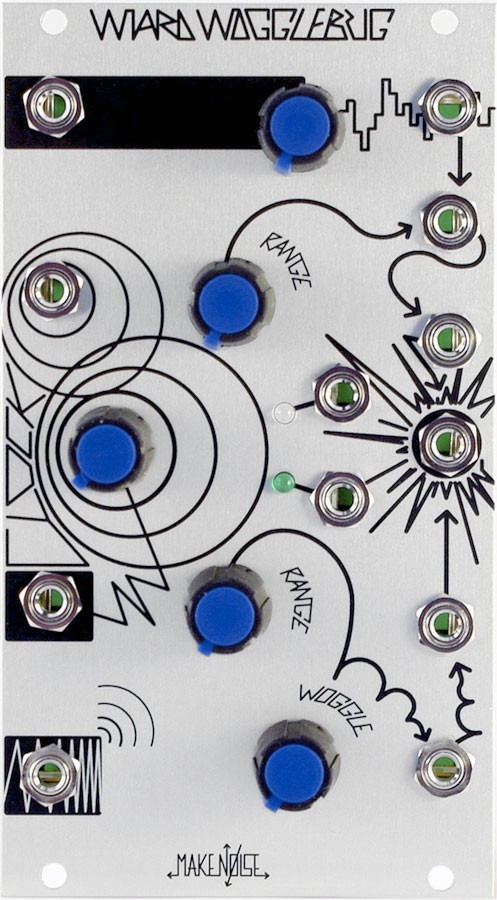 Pre-2014 Eurorack Wogglebug by Make Noise
The random voltage generation section includes a sample and hold circuit with a potentiometer that controls clustering. This is the range of possible values, so at lower potentiometer positions, it only lets low voltage values through and as you increase the position, it will increase the total range of possible values. At lower settings, patterns tend to emerge as the outputs values cluster together. This is achieved by a similar method as the Buchla 265 stored random voltages, where the output of the sample and hold is fed back into itself through a potentiometer which crossfades between the output of the sample and hold and the internal random. The internal source for the sample and hold is a sawtooth wave generated from the PLL that is modulated by the sample and hold output via a vactrol.
It also has a linear slew generator that follows the stepped random voltage with a rate is set by the clock control. When using an external clock, you can use the clock controls to control the slew time. Where the Wogglebug gets really interesting, though, is its Woggle CV output. It’s a slewed CV signal derived from the slewed random voltage...but instead of linearly following the voltage, it instead travels in sinusoidal wiggles around the voltage level. When it catches up to the stepped level, it sort of "woggles." Both the smooth and woggle outputs use the demodulated outputs from the PLL chips in order to achieve the slewing effect, but in different configurations.
The final section is the audio section, which has a VCO controlled by the smooth CV, a VCO controlled by the woggle CV, and both of those signals ring modded together via XOR logic. The XOR output is referred to by Grant Richter as “Child tones.”
The Make Noise Richter Wogglebug is a Eurorack adaptation of the Wogglebug. It features a burst output, which outputs random bursts of gates, influenced by the other panels controls. It also features a button that stops the clock, causing the outputs to hang. With a dummy cable patched into the clock input, the button can be used to trigger new random outputs at each press of the button. Audio or CV signals can be patched to the external input. The Clustering control (the ego/id knob on the Make Noise module) controls the balance between the internal sampling and the external input.
If you’ve ever owned a Wogglebug, you are lifelong members of the Royal Order of the Wogglebug.
Grant Richter's Random Part 2: Noisering
Another module from the mind of Grant Richter is the Noisering. The Noisering was a Frac rack module, which is a similar size to Eurorack modules but has different power standards and cases. Instead of sample and hold, it uses an eight-bit shift register to generate random voltages. It has controls for the internal clock as well as Change and Chance. It uses comparators with a DC offset and white noise in order to generate the data for the shift register. The chance setting controls the likelihood a high bit of data is added to the shift register. The change controls whether the data from the last bit of the shift register is recycled back into the register or if a new value is selected. Output 1 is similar to Buchla's n+1 and provides nine voltage levels, and output two is similar to Buchla's 2^n, providing 256 voltage levels. Malekko Heavy Industries released a Eurorack version of the Noisering that adds an external clock input.
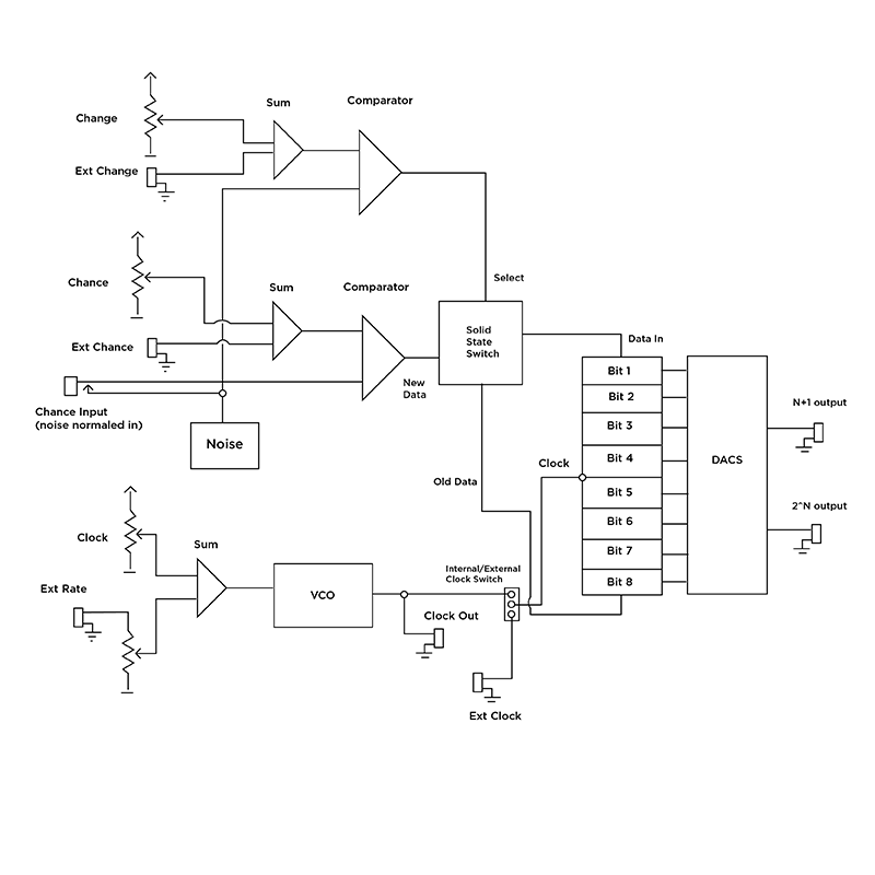 Noisering block diagram
The Music Thing Modular Turing Machine and the Grayscale Permutation follow the noise normalized into shift register architecture. The change control sets the amount randomness allowed into the register by setting the voltage threshold for the internal comparator. Noise is routed into the comparator input; with the change knob in the middle, it allows a constant stream of new data into the shift register. The Turing Machine does something not a lot of the other sources of randomness we’ve covered do, create looping patterns. These patterns can be locked using the knob, which also can be used to add little bits of randomness to the looped pattern. It makes a kind of random that is very playable and musical, not an uncorrelated stream of values. With the knob all the way to the right or left, the Turing Machine locks the sequence by recycling the bits of the shift register into its data input. An eight-position rotary switch selects the length of the recycled stream of data from a two to 16 (not all values between two and sixteen are available) step sequence of values by selecting which of the shift register’s bits are fed back.
The output of the comparator and the end of the loop of the shift register are fed into a series of bi-lateral switches. The bi-lateral switches have two channels that can be inputs or outputs that can be turned on and off with a control signal. The compared noise output controls whether or not the end of loop gets recycled back into the register via the bi-lateral switches. The Grayscale Permutation series builds on the Music Thing Modular design and adds bipolar VCA with level control and controls for adding to and clearing the internal data.
Rob Hordijk's Rungler
Another esoteric source of randomness is Rob Hordijk’s Rungler circuit. It is featured on the Benjolin, Blippoo Box, and as a 5U module in the Hordijk system. Though implemented differently in each design, in its basic form, it is based on two oscillators that feed the clock and data inputs on an eight-bit shift register. The last three bits are fed into a simple digital to analog converter, an R2R resistor ladder, touched on in the first random article. It produces a stepped bipolar CV signal, referred to by Rob Hordijk as a stepped havoc wave. This CV signal is fed back into the two oscillators, modulating their frequency. Additionally, in each iteration, the two oscillators can also modulate each other.
One important aspect of this configuration is the addition of attenuators for the CV modulation level. Fine tuning and control over the amount of chaotic modulation is key in making subtle and musical results. The Rungler falls into repeating patterns that change and evolve over time. Every time the controls are changed, it goes into a new unbalanced state, and attempts to find a balanced state, a stable pattern where it can stay. The new balanced state is defined by the exact position of the control knobs, plus the previous state it was in. In the three-bit implementation found in the Benjolin, it produces nine possible CV levels, which may seem limiting, but offers up a very musical response. (I'm not sure how Rob got nine voltage levels from a three-bit signal, but if he said it has nine voltages, I believe him.) Rob Hordijk describes the Rungler as "bent by design," referring to its tendency to produce seemingly lo-fi chaotic results not unlike those achieved by circuit bending.
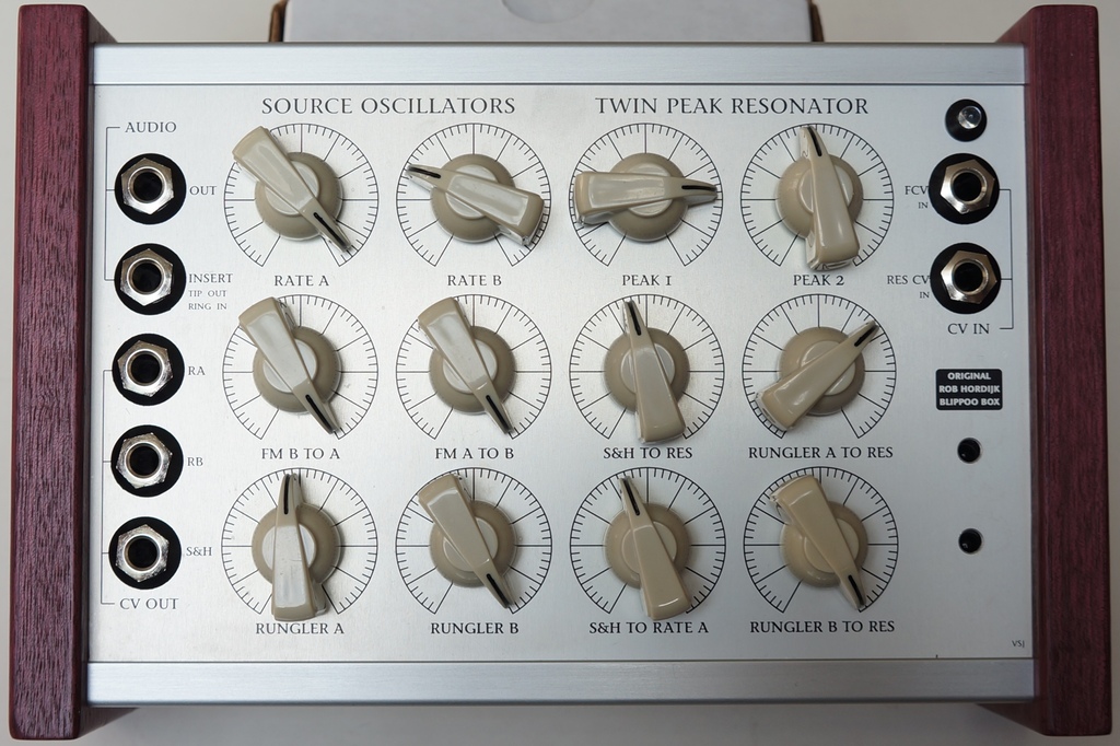
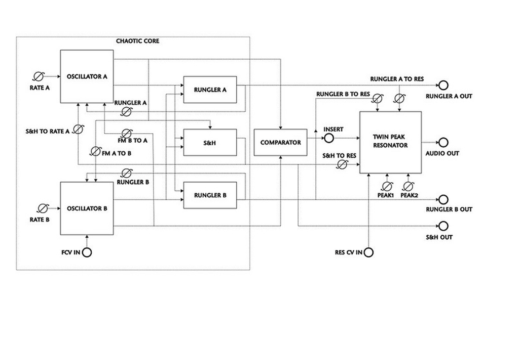
The 5U iteration of the Rungler has three modes: random, sparse, and dense. Random provides constant change when the data oscillator is a lower frequency than the clock oscillator, and becomes locked to a repeating pattern when it is higher. In sparse mode, the clock oscillator is very slow and will output a pattern of 32 notes. In dense mode the chaos increases as the data oscillator’s frequency increases: there is no locking. The Blippoo Box adds a sample and hold fed by the two oscillators that adds another layer of modulation. The two oscillators are fed through a comparator and that output is routed through a Twin Peak resonator. The Twin Peak is a filter with two independent low pass filters that share a common resonance control. The two filters' outputs are subtracted from one another—so their cutoff controls create a bandpass filter that only passes the frequencies between the two cutoff points.
One module that is inspired by the Rungler is the (now discontinued) omiindustriies Dual Digital Shift Register. It features two four-bit shift registers that feed a digital to analog converter, done in a similar way to the shift register implementation in the Rungler. However, any signal can be used to clock and supply the data to the shift registers, making complex Rungler-type patches possible with any module in a Eurorack system.
Software Randomness
Now in the 21st century, digital implementations of randomness can be done in software. Many sequencers now include controls for probability. Some random generators include quantizers to reign in their aleatoric nature and constrain them to musical scales. Other random voltage sources model random behaviors that would be too complicated or expensive to implement in an analog-only hardware setting. Novel algorithms are abundant, and it would be impossible to address all of them—but we wanted to take note of some of our recent favorite implementations of interesting random and chaotic signal generation.
 Lorenz attractors visualized
Ornament and Crime includes modes such as an analog shift register with scale quantization as well as Lorenz and Rössler chaotic signal generators. The Lorenz and Rössler attractors are differential equations that are mathematically deterministic but result in chaotic behavior. When plotted on an XY axis, the path of the attractors makes a double well pattern, orbiting two different points and moving back and forth between them.
The ADDAC402 Heuristic Rhythm Generator has functionality for a number of random gate and trigger generation schemes. One of the most interesting modes is based on John Conway’s Game of Life, a cellular automata-based "game." Cellular automata is a branch of mathematics and computer science in which a simple set of rules determines the behavior of a grid of cells by assessing the state of the neighboring cells. The cells only have two states, on or off. (There are some forms of CA in which the cells have more than two states, but in this case we're just looking at binary elementary cellular automata.) In the Game of Life, these states are referred to as alive or dead. This can manifest in complex results from a very basic set of operating rules. The rules of Conway’s Game of Life are as follows:
- Any live cell with fewer than two live neighbours dies, as if by underpopulation.
- Any live cell with two or three live neighbours lives on to the next generation.
- Any live cell with more than three live neighbours dies, as if by overpopulation.
- Any dead cell with exactly three live neighbours becomes a live cell, as if by reproduction.
 The Game of Life visualized
Reflections of cellular automata rules can be seen in nature such the patterns of certain sea shells and the regulation of gaseous respiration in plants. Different rules have different results and can vary from static and predictable to chaotic and ever changing. On the ADDAC402, the length of a trigger/gate pattern can be set for each of the four channels. Doing so will randomly fill in the pattern with cells that are alive or dead. With the press of a reset button or corresponding trigger input, a new pattern is generated based on the rules of the Game of Life. This creates evolving and aleatoric patterns that are both random and deterministic.
Another ADDAC module, the ADDAC503 Marble Physics models the physical properties of a marble in a two-dimensional space. The speed and X and Y position of the marble can be controlled, as well as the elasticity of the “walls” of the space the marble resides in. The marble can be bumped, which kicks the marble into gear, with a control to adjust the strength of the bump. While not truly "random," this can manifest complex and unexpected results
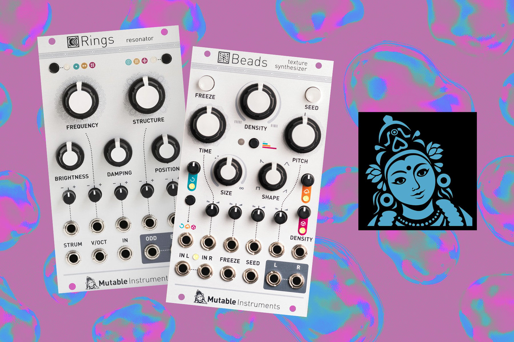
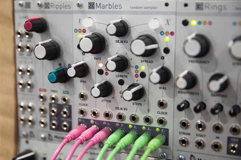
Mutable Instruments’ Marbles (unrelated to the ADDAC module), recently discontinued, is a powerhouse of digital randomness. It features a clock section and a voltage section. The clock section includes a master clock with output (labeled T2), two gate outputs (labeled T1 and T3), jitter control, and three probability modes. The three probability modes are Bernoulli gate (derived from the Branches module), multiply/divide, and snare/kick patterns (derived from the Mutable Instruments Grids). The Jitter control humanizes and shuffles the clock signal, while still retaining the overall timing. The Bernoulli gate mode basically acts as a coin toss, selecting which one of the two outputs passes the incoming signal, in this case the clock signal for the module. The bias or distribution knob sets the probability. In the middle, the two channels have equal weighting, and turning the knob left or right increases the likelihood that the respective channel will be selected and output the clock. In multiply/divide mode, the two gate outputs are generated by randomly dividing and multiplying the clock speed. The bias knob sets which output gets multiplied and which one gets divided. In the kick/snare mode, the outputs swap at a rate set by the bias control, producing what are often called linear drum beats (where the kick and snare don’t fall on the same beat, but in this case are randomized). In any of these modes, the output pattern can be locked using the T button.
The X section is the random voltage section. It has controls for distribution, bias, length, and step slew/quantize. The step control controls both the slew rate and quantization. To the left, the control adds slew to the random voltage outputs. To the right, it begins to quantize the random voltage outputs to a chromatic scale. Further turning the knob gradually removes notes from the scale, until only octaves of the root note are present. The spread and bias control the probability distribution and offset of the random outputs. With the spread knob in the middle, the distribution follows a bell curve, with voltages appearing concentrated in the middle, but still with the possibility of extreme voltage outputs. To the left, the distribution concentrates to the middle of the range, with a constant output level at the center of the output range at the lowest setting. To the right the voltages begin to occupy a more equal distribution, but at higher settings only the lowest and highest values are present, essentially turning the X outputs into random gates. The bias further skews the distribution higher or lower with a center offset and works in conjunction with the spread. The T1, T2, and T3 outputs clock the corresponding X1, X2, and X3 random voltage outputs. This is reminiscent of the triple sample and hold and pulse divider on the Buchla 266. The Y output is a smooth random source, with a range of +/-5 volts. By default, Y is clocked at 1/16th the rate of X2, but it can go from 1/64th the rate to an undivided rate of X2.
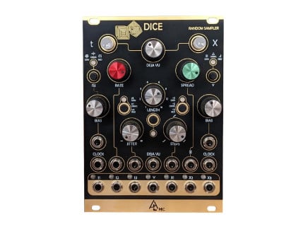
Though Mutable Instruments is no longer operational, the core functionality of Marbles is preserved in modern third-party adaptations such as After Later Audio's Dice, a direct recreation of Marbles, and Cara, a direct functional translation with a smaller physical footprint.
Whenever Marbles needs to make a decision about a random setting, it checks the Deja Vu section. This can be turned on independently from either the T or X side using the buttons. From lowest settings to the middle, the probability settings for from zero, completely random to one, recycling the locked loop of data. This works in a similar fashion to the stored random voltages on the 265 or the change knob on the Turing Machine. To the right of the center position, the data is recycled but randomly jumps around within the locked sequence. No new data will enter the random pattern, but the behavior of this locked pattern is randomized. The length control sets the length of the looped data. Y is not influenced by the deja vu section.
Digital Euro Random Sources
 Plum Audio OCP X 3U Ornament & Crime 10hpAs low as $349.00Multiple Options Make a selection for stock info
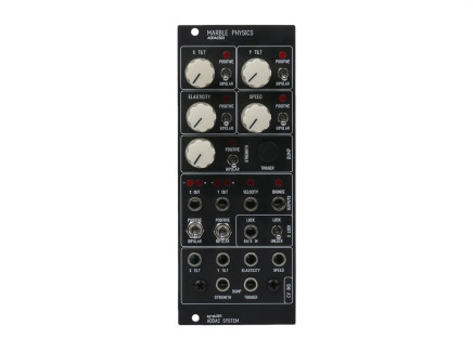 ADDAC System ADDAC503 Marble Physics 10hp$439.00Preorder Reserve your order today!
Out of Stock
We're awaiting our next batch of this item. Pre-order to reserve your place in line and we'll fulfill your order as soon as we receive our shipment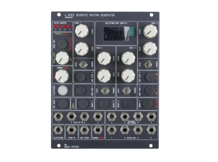 ADDAC System ADDAC402 Heuristic Rhythm Generator 20hp$569.00Preorder Reserve your order today!
Out of Stock
We're awaiting our next batch of this item. Pre-order to reserve your place in line and we'll fulfill your order as soon as we receive our shipment
We’ve explored a lot of different schools of thought about randomness. From hardware to software, sample and holds and shift registers, this weird aspect of modular synthesizers has baffled and captivated the minds of users for generations. The ghost in the machine of modular that seems to have a life of its own might seem a bit less daunting after these articles. I hope you’ve found them useful and have a new appreciation for what synthesizers can do with a little guidance. It makes music making into a collaboration with the machine, a conversation where you have one idea of what you want and the circuits have their own, and what meets in the middle, well, that’s where the magic of synthesis happens.