The previous article covered some of the ways in which randomness is generated in a modular synthesizer setting. In this article we’ll be going over some of the specific modules that produce these random outputs. This includes historic modules that are no longer readily available and some of their modern counterparts.
Although we are not limited to the technology of the past, understanding the history of a technique can provide new insights and inspiration for its use. As such, we return to an old friend: one of the most influential designers who has informed the way we think about randomness in electronic music today is, of course, Don Buchla.
Buchla’s Source of Uncertainty and Its Evolution
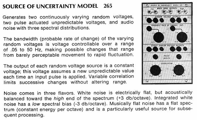 265 details from vintage Buchla brochure
One of the best-known Buchla modules is the 266: the Source of Uncertainty. It deviated significantly from the traditional white-noise-to-sample-and-hold style of randomness, adding extensive control over the timing and level of predictability of its random outputs. Finally, randomness was able to be fine-tuned and controlled like any other part of the synthesizer—providing access to altogether new techniques for synthesists, based on stochastic and rule-based implementation of probability. Suddenly, randomness was no longer just a toss of the dice: the 266 made it possible to determine just how many sides the dice had, and which sides were most or least likely to come out on top. However, Don Buchla didn’t start with the 266...it evolved over several iterations.
Buchla’s random voltage sources started with Buchla 165, a remarkably stark design in comparison to his later output. It consisted of two channels, each with a trigger input and two uncorrelated random voltage outputs. No other controls were available, nor was the ability to patch in external signals for sampling—just send a pulse in and get stepped random voltages out, plain and simple. Subsequent 200 Series modules provided dramatic re-imaginings and expansions to the possibilities of the 100 Series—and the 265 Source of Uncertainty is no exception. This module is not the "Source of Uncertainty" that most of us know and love—and it can be seen historically as a stepping stone between the stark, simple 165 and the iconic 266. The 265 features a fluctuating random voltage section (then just called random voltage outputs), stored random voltage section, and three noise types.
The fluctuating random voltage section is a brilliant design which produces continuously-varying, wavering control voltages with manual and voltage control over the Probable Rate of Change.
It uses a sample and hold that samples a noisy triangle wave based on an internally controlled clock. The output is lowpass filtered at a cutoff frequency based on the speed of the clock oscillator. It uses a 100hz triangle wave synced to noise rather than just white noise, so it has relatively even distribution across its entire voltage range. (The distribution of white noise is more concentrated at the middle of the frequency spectrum, so syncing the triangle oscillator to noise offers a more equal distribution while still retaining randomness.) The speed of fluctuation can be defined anywhere between .05 to 50 times per second...so it can produce long, gradual changes up to rapid, spastic modulations.
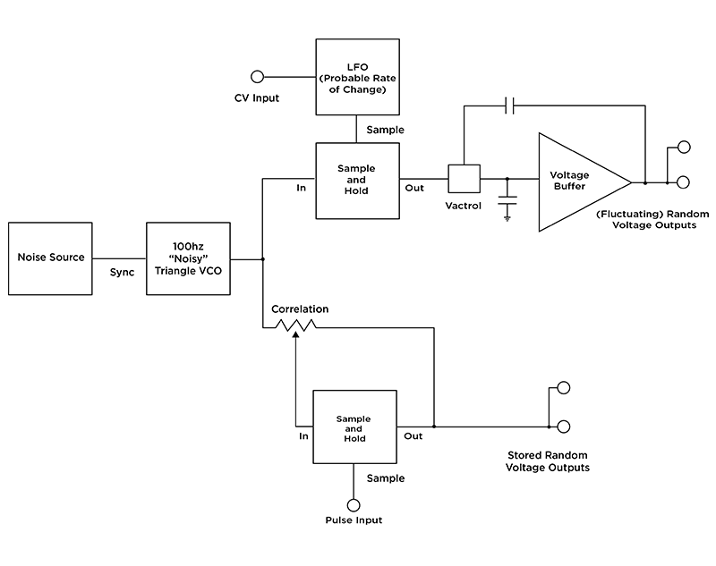 Simple Buchla 265 block diagram
The stored random voltage section on the 265 is a sample and hold that uses the same noise-synced triangle wave technique as the fluctuating random voltages, but produces stepped rather than smooth output voltages. It features a pulse input and two random voltage outputs—a feature set not dissimilar to the previously discussed 165. But it also features a correlation control that goes from 0 to 1—and this control is a bit odd. "Correlation" is basically a cross fader between the noise-synced triangle wave and the output of the sample and hold. At zero, the output changes randomly from one value to the next based on the external clock input with no correlation to the previous voltage level. At the max setting, the voltage doesn’t change at all, as it is just sampling itself. In the middle, the output is influenced by its previous states, with the Correlation position effectively defining how far the new random value can deviate from the old one—a simple, but profound way of implementing control of just how random the output is. This idea is blown wide open in the 266...which we'll address shortly.
The Buchla 212 Dodecamodule is also worth note here—essentially, the 212 was a collection of modules that provided studio functionality in a smaller package. By creating a single module with twelve submodules based on more fully-featured 200 Series designs, it made possible the creation of extremely compact Buchla systems, included the rare and peculiar System 101 (in many ways a seeming predecessor to the Music Easel). The 212 featured a random voltage section somewhat like half of a 265: it features stored random voltages, fluctuating random voltage, and two noise sources (labeled High and Low).
The 266 Source of Uncertainty
The model 266, the best known Source of Uncertainty, developed profoundly on the capabilities of the 265. It has several sections: noise, fluctuating random voltage, quantized random voltages, stored random voltage, an integrator, pulse divider, and a collection of sample and holds. Most notably, the 266 added voltage control of probability distribution, quantized randomness, the addition of a voltage controlled integrator, and a unique implementation of an otherwise vanilla sample and hold.
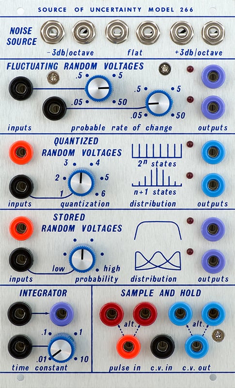 Front panel detail of a modern adaptation of the Buchla 266
The noise outputs are pink, labeled as -3db/oct; white, labeled as flat; and blue or reciprocal white noise, labeled +3db/oct. This sounds a bit like filtered pink noise, but instead of band limited, the energy of the noise is redistributed. The second section is a pair of fluctuating random voltage generators. This is functionally the same as the fluctuating random voltages found on the 265.
The quantized random voltage section is where things start to get particularly interesting. It has two outputs which generate a voltage at the output every time it receives a pulse. This section is one of the 266's most unique features, basically providing the user the ability to limit the number of potential values that the outputs could produce (rather than the technically infinite potential values yielded from noise and a sample and hold). One output is labeled n+1, and the other is marked 2^n. N is a numerical value between 1 and 6 and is defined by the panel control and external control voltage.
So what does "n" mean in practical terms? Well, if n=1, then the n+1 output can produce two different values (as 1+1=2), and the 2^n also can produce those same two values (as 2^1=2)—but aside from timing, these outputs are uncorrelated. If n=2 then the n+1 output would choose between three values; the 2^n output, however, would choose between four values (2+1=3, but 2^2=4). With 3 selected, the n+1 is 4 and the 2^n is 8, etc. The n+1 output scales linearly which the 2^n output scales exponentially. Again, these two outputs are correlated in time but produce different values, leading to interesting combinations of values and notes. This type of rule-based randomness breaches into stochastic behavior: that is to say, the output is random, but provides some form of control over the probability that particular values/states will occur.
The 2^n section has equal distribution over the entire range while the n+1 distribution favors the middle values (hence the associated "distribution" graphics on the front panel). It uses a 6-bit shift register in order to make a 64-step pseudo-random sequence that repeats infinitely. The Buchla 208 Stored Program Sound Source (half of the Music Easel) uses a similar implementation of a shift register based pseudo-random voltage generator, although it is done differently and does not feature control over the random voltages produced apart from a trigger input.

The stored random voltage section has two outputs which produce random voltages when the section receives a pulse. (Note: although it shares the name with the 265 stored random voltages, it is implemented differently.) The top output generates random voltages according to an even voltage distribution. The bottom output, though, has a potentiometer and cv input to determine the random voltage distribution. WIth the distribution pot in its lowest setting, most of the output voltages will be in the lower range with occasional higher values. As the potentiometer or control voltage input is increased, the concentration of random voltages moves from medium voltages to higher voltages. In the audio expample to the left, a Verbos Random Sampling's 2^n and n+1 outputs are sent to two oscillators' pitch inputs, with the "n" value first changed by hand and then modulated. It results in all sorts of peculiar arpeggios and random melodies—but of course, it could just as well be applied to any aspect of sound.
The last two sections are a pulse divider, a trio of sample and hold modules with single sample input, and a voltage controlled integrator. The pulse section has a pulse input and two pulse outputs. On every clock pulse, one of the pulse outputs goes high and the other goes low, on the next clock pulse they alternate with the second pulse output goes high. This could be used as a divide-by-two clock divider or a steady kick and hat combo for some rockin’ techno. There are three sample and holds with a common sample input: one is clocked from the direct input pulse and the other two are clocked by the alternating pulse outputs. The integrator is a slew generator and has a single input and output, with control for time constant (slew rate) and CV over the slew rate.
The 266 is a perfect example of the functional density and clever design that has kept Buchla's name among the most highly-revered electronic instrument designers. The 266 allows performers and composers to relinquish some aspects of compositional control—but also, to determine just how much control is relinquished. This was a significant step forward from basic sample and hold techniques, providing a control over randomness that fascinates musicians to this day.
Sources of Uncertainty in Eurorack
While vintage 266s are difficult to come by (and quite valuable), many current Eurorack manufacturers have looked to it directly for inspiration. Eurorack has provided a more affordable/accessible platform for exploring countless musical ideas—and many of Buchla's original concepts have found their way into the Euro ecosystem. The Source of Uncertainty is no exception
 Verbos Random Sampling, heavily influenced by the Buchla Source of Uncertainty
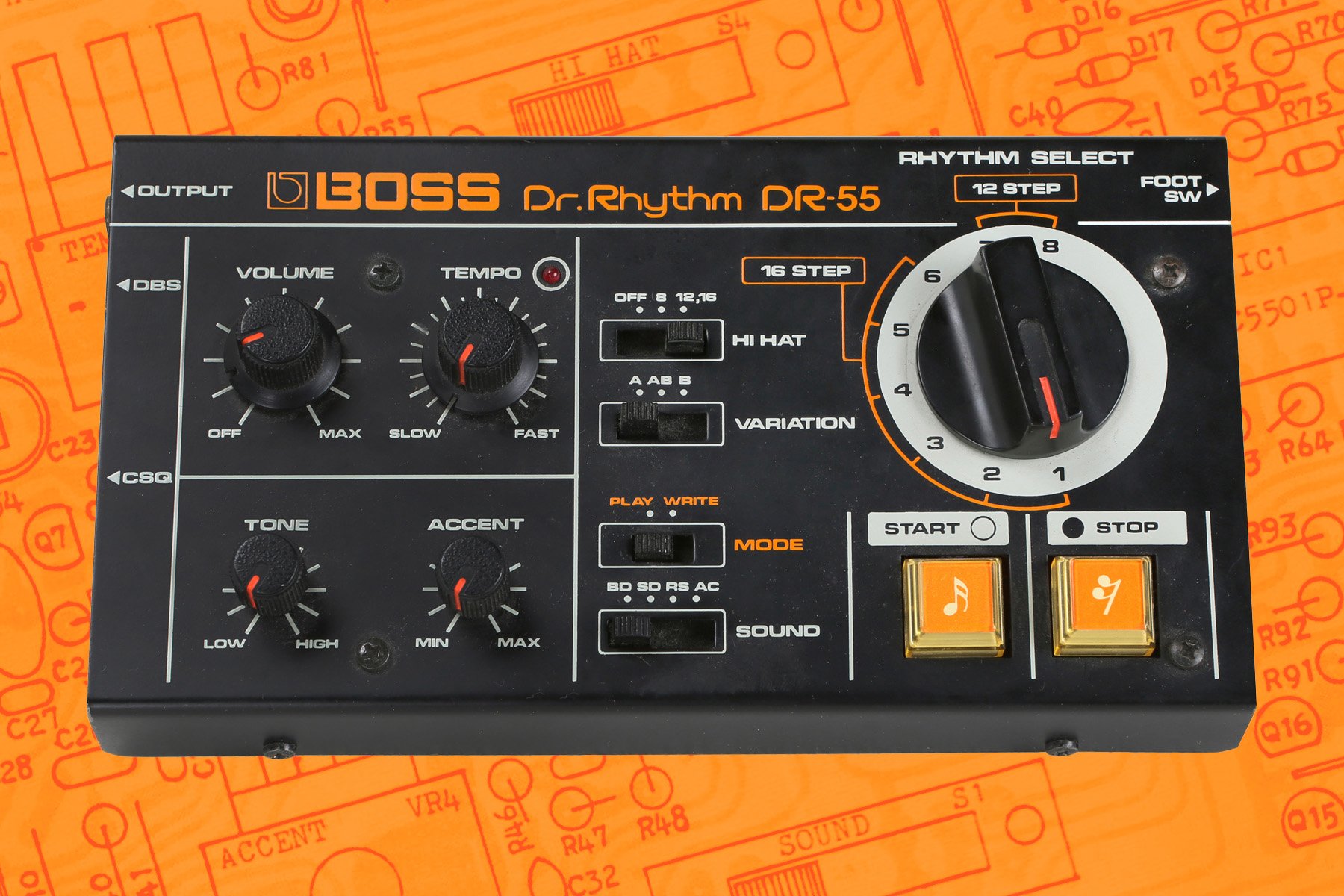
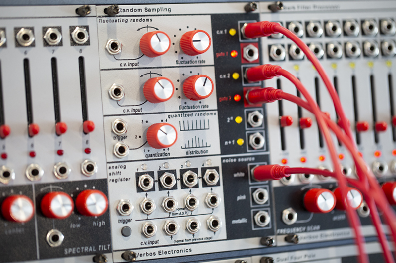
One of the most obvious translations is the Random Sampling, a member of the heavily Buchla-influenced Verbos Electronics family of modules. A quick look at the panel will reveal familiar terminology: Fluctuating and Stored Random, n+1, 2^n, etc.—but it does bear several differences from the 266 as well. The Random Sampling uses a much longer shift register in lieu of the 64-step pseudo-random sequence of the 266, and also eliminates the integrator circuit. Added features include a four-stage analog shift register (not unlike the "Fortune" ASR mentioned in the previous article), gate outputs from the fluctuating random, and another flavor of noise: metallic, which is a series of detuned square waves that are XOR’d with each other. This pseudo-noise technique is found on analog drum machines such as the TR-808’s cymbal. The analog shift register has a common trigger input and CV input that is normalized down the four stages but each of the channels can be used independently with individual inputs for triggers and CV.
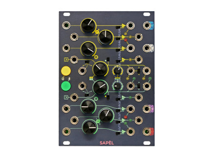
Sapel from Frap Tools is another module that takes inspiration from the 266, but calls itself “tamed random.” It features two channels each with 2^n, n+1, fluctuating random voltages, and unquantized sample and hold outputs—making it not unlike two 266s behind one panel. Additionally, it features an internal clock, input for external clock or hold, and random gate output. The n+1 output quantizes to integer voltages at one volt increments, providing clean random octaves when applied to a 1V/Oct pitch control. The 2^n output is quantized to semitones. There is a probability control that influences all three channels of random, with switches to turn the weighting on or off. The probability density is related to the 266’s stored random voltage distribution settings.
The module can be clocked internally or externally. A switch controls whether the random gates are slower than the clock signal or produced on every pulse of the clock signal, plus bursts of gates. The fluctuating random voltage control influences the clusters of random gates. A button is present which holds the outputs at their current level. A switch controls whether the gate signal goes to clock the module externally or turn on and off the freeze function.
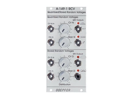
The Doepfer A-149-1 is very straight forward, in the standard Doepfer fashion. It has two sections, quantized random voltages and stored random voltages, adapted from the 266. It features both manual control of the distribution and CV control with attenuation, and bears the familiar nomenclature and iconography of the 266. It dispenses of the fluctuating random voltages, integrator, and sample and hold section from the 266...but it does provide some Buchla-like functionality at an excellent price.
266-Inspried Eurorack Modules
 Frap Tools Sapel Tamed Random 18hp$499.00Preorder Reserve your order today!
Out of Stock
We're awaiting our next batch of this item. Pre-order to reserve your place in line and we'll fulfill your order as soon as we receive our shipment Verbos Electronics Random Sampling 18hp$609.00Preorder Reserve your order today!
Out of Stock
We're awaiting our next batch of this item. Pre-order to reserve your place in line and we'll fulfill your order as soon as we receive our shipment
Randomness in the Serge Ecosystem
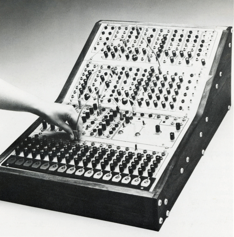 Serge system from a product mailer, c. 1990
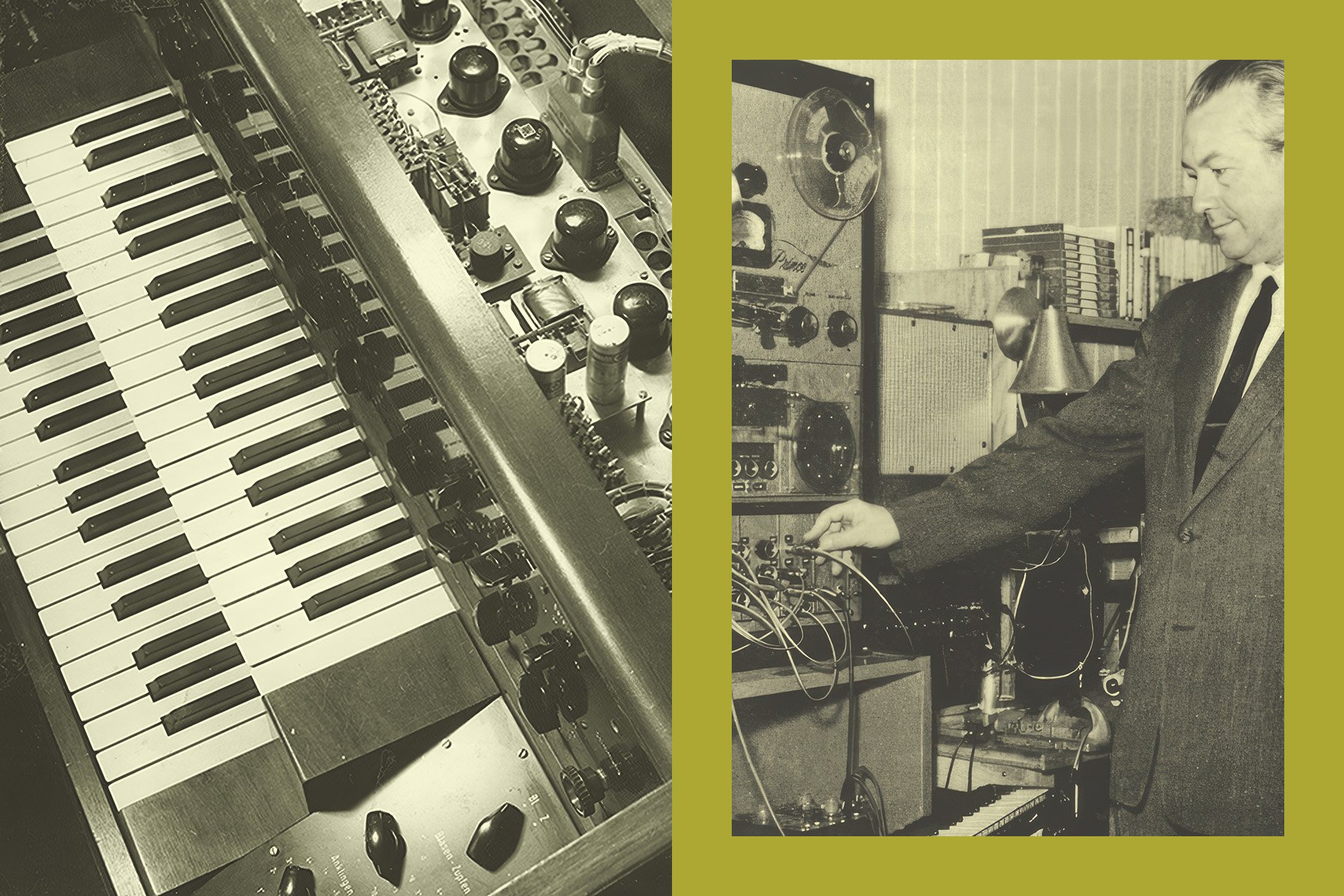
One of the other early champions of randomness and chaotic control in synthesizers was Serge Tcherepnin, developer of the Serge Modular Music System. While on faculty at the California Institute of the Arts, Serge developed an extremely open-ended modular ecosystem called The People's Synthesizer: so named because it brought advanced synthesis capabilities at a tiny fraction the cost of similar instruments, such as Buchla's then-new 200 Series. Eventually, the People's Synthesizer evolved into the Serge synthesizer. Directly inspired by the functionality of Buchla's instruments, Serge's designs sought an even more extended level of user control through a concept referred to as patch programming.
Patch programming is a concept popularized by Serge synthesizers where the function of the module can be changed by patching the module into itself or with another module. Serge modules often bear names and interfaces that do not immediately suggest a typical synthesis function, instead favoring open-ended designs from which typical functions can be patched together. It takes some getting used to, but in the end can provide uncommon flexibility from even a small group of modules. Serge's instruments are still praised for their functional density: some modules can act as an oscillator, filter, envelope, LFO, sample and hold, comparator, and more when patched appropriately.
Serge Noise Source and SSG
The typical Serge method of random voltage generation actually uses two modules with extensive options for patch programming. The two modules used for random voltage generation are the Noise Source and the Smooth and Stepped Function Generator (the SSG). The noise source is fairly straightforward: if offers pink noise, white noise, and S/H Source, a special type of noise designed for use with sample and hold modules in order to guarantee uniform distribution of random voltages—although you could use any of the noise outputs for sample and hold, of course. Additionally, the Noise Source typically provides a stepped random output, which can be triggered via an incoming pulse or a panel-mounted button.
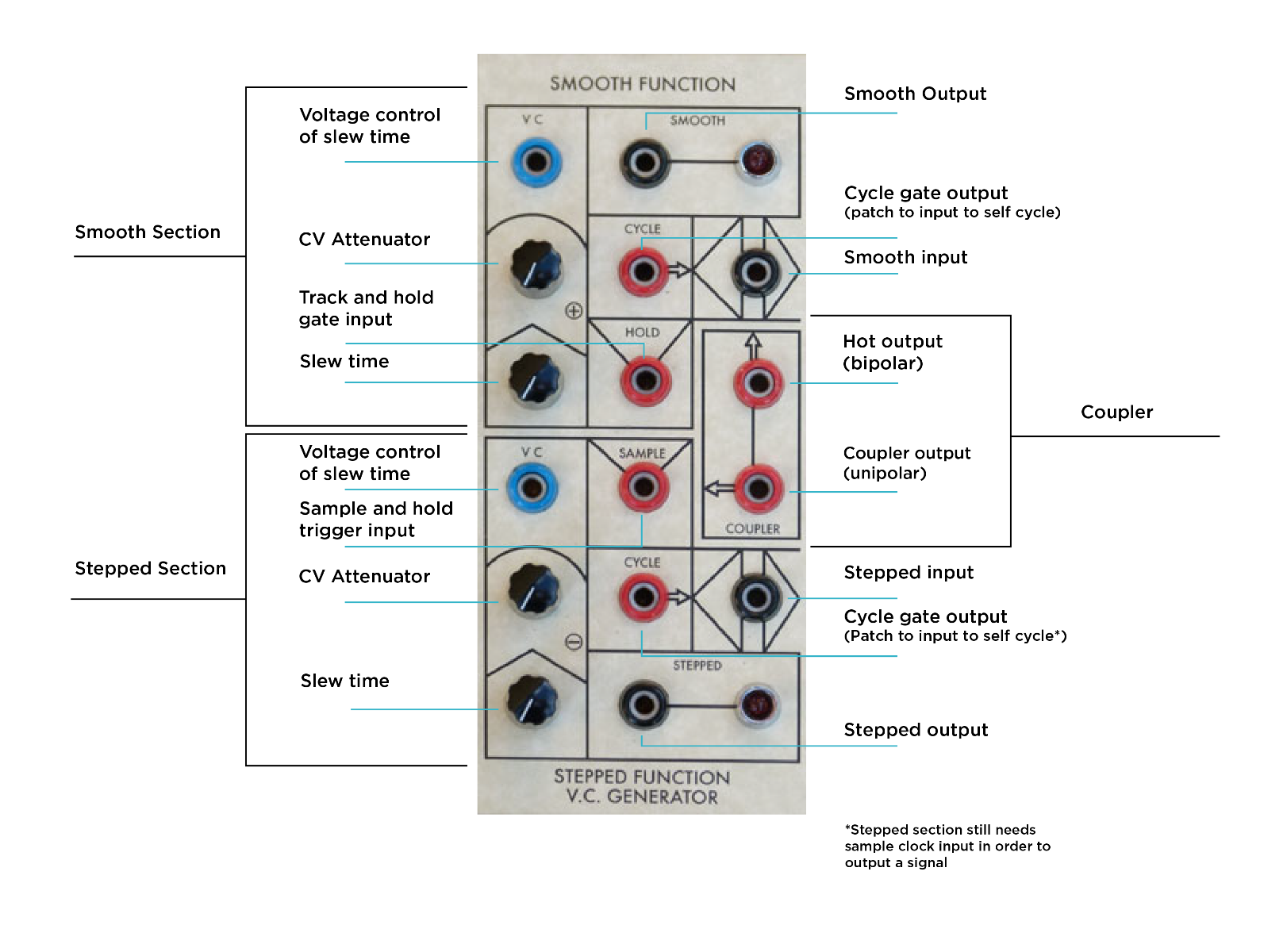 Serge SSG cheat sheet
The Smooth and Stepped generator has three sections. The Smooth section slews incoming voltages with a control voltage input for slew time. The cycle output is high by default. It goes low when the slew reaches a high threshold and goes high again when the slew reaches a low threshold. The module can self-cycle by patching the cycle gate output into the input, creating a triangle wave LFO at the smooth output and a square wave at the cycle output. (This is a classic example of the patch programming concept mentioned above). The Smooth function generator has a hold function, which is a track and hold. We covered track and hold in the previous article but just as a refresher, track and hold is almost the opposite of sample and hold. In a track and hold circuit, all voltages are allowed to pass through unaffected until it receives a gate signal, at which point it freezes the output at the current value and holds it there until the gate signal goes low.
The Stepped section has a sample and hold input, a slew rate limiter which limits the size of the step at the output and adds slew to the incoming signal. When the cycle output is patched back into the input and a trigger is sent to the sample and hold trigger input, you get a stepped or kind of staircase LFO. The slew of the stepped section does not affect the output voltage, but rather slews the incoming signals before the sample and hold—making it possible to control how closely the stepped output tracks the sampled voltage. This can lead to everything from traditional sample and hold at high slew rates, or extremely incremental changes in output value at slower slew rates.
The coupler is a comparator that compares the stepped and smooth output and outputs a high signal when the stepped is higher than the smooth output. It features two outputs, one unipolar (positive going only) and one bipolar (both negative and positive voltage). You need to patch from the noise to the Stepped and Smooth Generator in order to create the classic sample and hold sound, but the panel controls and patch programming allows you to generate new combinations of functions to make the random sequence more complex.
Using all sections of the SSG in tandem can produce three correlated random voltages at the same time. The classic random voltage generator patch as described by Serge Fans website: Patch the sample and hold source of the Serge Noise Source to the input on the stepped side of the SSG. Mult a signal from the coupler and patch it to both the sample input of the stepped side and the smooth input. This simple patch results in stepped random voltages, smooth random voltages, and random pulses from the coupler.
Serge Random Voltage Generator
 The Serge Noise Source and Random Voltage Generator, conveniently side-by-side
This brings us to an interesting point: many vintage Serge systems include another module for random voltage generation...the aptly-named Random Voltage Generator. This module provided a smoothly fluctuating random output, a stepped random output, and a random timing pulse output (in time with the stepped section). It provided a CV input for the rate of randomness, which affected all three outputs simultaneously.
If you look closely, you'll notice that the RVG in vintage Serge systems always seems to be positioned directly next to the Noise Source module—and that is because the RVG behind the panel actually is a Smooth and Stepped Function Generator. RVGs were built using the same circuit board as the SSG: instead of connecting banana jacks to all the appropriate patch points, one would instead permanently "program" the patch on the PCB by internally wiring the S/H Source to the Stepped generator input and the coupler to the Hold and Smooth inputs. This is the case in a number of other Serge modules—by wiring a single general-purpose PCB in different ways and applying different graphics/surfacing different connections, a simple circuit could be turned into several different modules.
Of course, then, the RVG's functionality is identical to the SSG random voltage generator patch...so if your Serge system seems to be missing random voltage functionality, take a turn toward your SSG.
Serge-Like Randomness in Eurorack
The Random*Source Smooth and Stepped Generator is a faithful adaptation of the classic Serge SSG. It features the addition of a cycle switch which eliminates the need to patch the cycle output to the input. It also features an expo switch, which changes the slewing curve to an exponential response. This is achieved by routing the CV output back into the CV input, causing the curve to change. This can cause the SSG to stop oscillating if in cycle mode, especially if the CV attenuator is at its lowest settings. The Doepfer A-118 is a great noise source that complements the Smooth and Stepped Generator and can be used as a source for the stepped or smooth side.
The Make Noise Function, often just seen as the little sibling of their ultra-famous Maths module, offers some of the functionality found in the smooth section of the SSG. It features a track and hold input, labeled Hang. Like the SSG, it can also be used similarly to a sample and hold if the pulse width of the input gate is wider than 90%. Though more commonly compared to the Serge DUSG (another famous patch-programmable module), the similarities to the SSG are striking.
SSG-Inspired Eurorack Modules
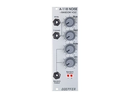 Doepfer A-118 Noise + Random Voltage 8hpAs low as $89.99Multiple Options Make a selection for stock info
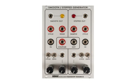
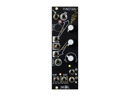 Make Noise Function Control Voltage Generator 8hpNo Longer Available Contact us for a recommendation.Out of stock
These techniques of random voltage generation have had lasting impact on the world of synthesis. We see their influence in modular synths that are being produced today, many of which take these concepts and build upon them. The third article in this series will go over some of the more modern approaches to randomness in modular synthesis that go beyond what was imagined and what was possible in the 1970s.