Randomness in modular synthesis opens up a whole new realm of music making wherein compositional decisions are taken out of the hands of the user and are granted in some way to the electronics. Its effects can range from subtle changes in the cutoff of a filter all the way to ever-evolving, self-playing patches that require no human hand to influence the outcome.
Sources of randomness in modern synthesizers can range from slow, continuously fluctuating changes to jagged, sudden changes in sound. In this article we’ll begin to look at the early uses of randomness in 20th century music and how those methodologies have influenced modern conceptions of synthesis. In future articles, we’ll go into further detail of the specific approaches to randomness in twentieth century synthesizer design from designers such as Don Buchla and Serge Tcherepnin. Finally, we’ll explore more modern conceptions of randomness, informed by these pioneers. For now, let’s take a look at the basics.
Origins
Randomness in modern music has many roots, some of which can be traced to the Dada art movement of the early 20th century, in which artists often eschewed tradition through a radical embracing of absurdity. Marcel Duchamp was one such artist, whose work and influence is still felt today. Originally a painter, Duchamp’s work also helped popularize readymades—found objects presented in a fine art context. Most famous of these was Fountain, a urinal rotated 90 degrees and signed as his pseudonym R. Mutt. Duchamp’s "Erratum Musical," one of his only musical works, was written for three voices. Duchamp made three sets of 25 cards, one for each voice, with a single note on each card. These were mixed in a hat and drawn at random in order to leave the composition of the piece up to chance. There are no rhythmic indications to tie the three parts together or an indication if they should even be sung together or separately. The second Erratum Musical, titled "La mariée mise á nu par ses célibataires, même" ("The Bride Stripped Bare by her Bachelors, even") uses letters and numbers in lieu of musical notation. According to Duchamp the piece is "unfinishable" and is intended for "a specific musical instrument (player piano, mechanical organ, or other new instruments where the virtuoso intermediary is suppressed)."
John Cage is perhaps the most influential proponent of chance music. He used everything from the I Ching to star charts in order to inform his compositions. Sometimes the element of chance was left to the performer, in pieces such as 0’00”; whose instruction is a single sentence that reads "In a situation provided with maximum amplification, perform a disciplined action."
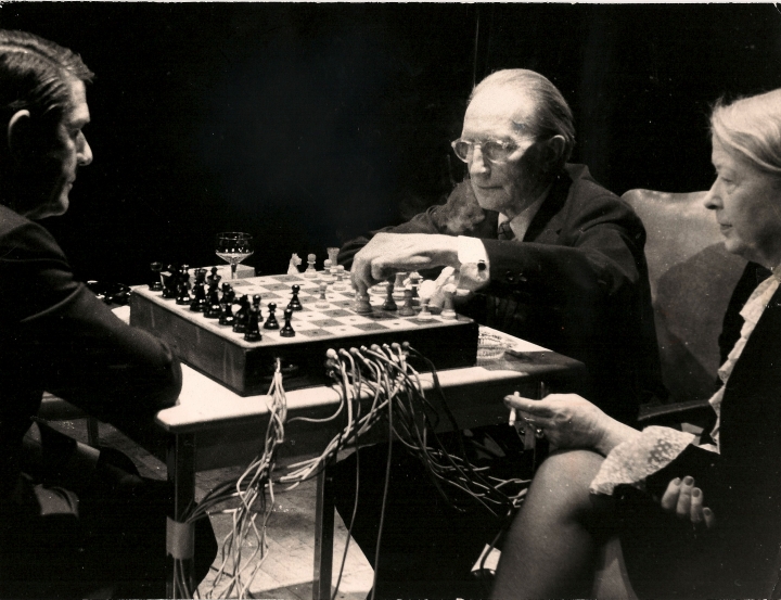 Duchamp and Cage performing "Reunion"
In 1968, Duchamp and Cage performed the piece “Reunion.” They played a game of chess on a specialized chess board built by Lowell Cross. The spaces of the chess board had photo sensors under them. The spaces would trigger or mute pieces of electronic music when a piece was placed on top of them. The music was composed by John Cage as well as Gordon Mumma, David Behrman, David Tudor, and Lowell Cross himself. Duchamp, a chess master, beat Cage in under half an hour. Duchamp’s wife, Teeny, and Cage played a game that lasted until 1 am...at which point the game was temporarily paused. Teeny eventually won the game when it resumed a few days later.
Early pioneers of electronic music Louis and Bebe Baron also collaborated with John Cage. Louis designed rudimentary electronic music making circuits and Bebe performed using them. Bebe captured the results on tape, which was further spliced, processed, and edited together. The rudimentary circuits used vacuum tubes for oscillators and amplifiers, diode based ring modulators, and lots and lots of feedback in order to create otherworldly sounds. Louis thought of his circuits as living organisms, going through their life cycles and inevitably dying (the components were pushed to their limits in order to create new tonalities; because of this the circuits frequently self destructed). The Barrons provided the first all-electronic film score for 1956's Forbidden Planet; however, they were not considered musicians by the Musicians’ Guild and were not initially credited as such.
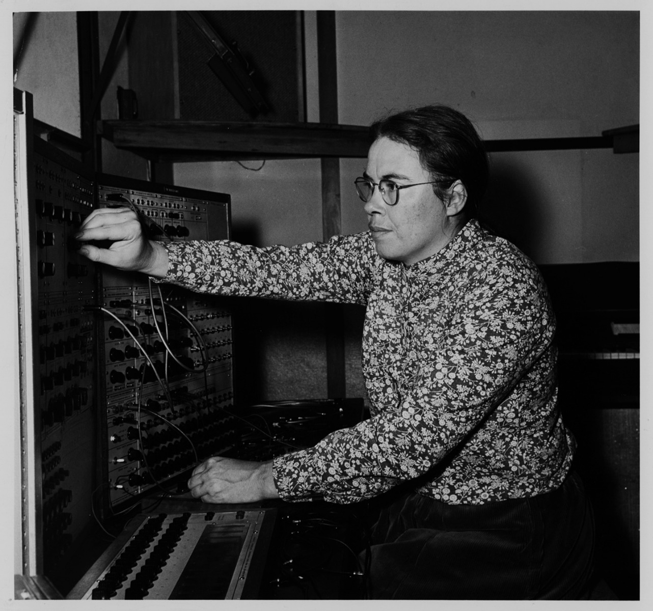 Pauline Oliveros with the Buchla 100
As more people were exposed to early electronic music techniques, artists began to want to push the boundaries further. The San Francisco Tape Music Institute was a collective of avant-garde artists working with sound and the medium of tape that was started by Pauline Oliveros, Morton Subotnick, and Ramon Sender. Its goal was to spread knowledge of tape as an artistic medium and to further explore its creative potential. In 1963, Don Buchla began working with Subotnick to develop an electronic music instrument that could create sounds hitherto unheard by humans, which became the Buchla 100 Series. This instrument also included new ways to compose music, moving beyond organ style keyboards...including random voltage generators.
Early synthesizers, though, were incredibly expensive and few could afford them: they primarily existed within the halls of academia and were outside the reach of the general public. Because of their close relationship with academia, synthesizers in the 1960s and early 1970s developed alongside a keen awareness of the experimental work of artists like Duchamp, Cage, and others (and only later began to change form to accommodate the needs of more popular genres of music). Instruments from this era were highly exploratory, often developed with the express intention of exploring not only new sounds, but new ways of composing and organizing music. As such, along with structures for creating highly specific results, they have always incorporated elements of randomness—allowing musicians to make the choice to relinquish some amount of control to forces they cannot predict, in order to produce results they otherwise might not be able to imagine. For many, this is a tremendous source of inspiration: rather than planning out every detail of a sound, using randomness can allow them to focus on listening more so than planning, placing their perspective closer to that of the audience than might be possible otherwise.
This in mind, let's now take a closer look at a few of the most common techniques for producing randomness in analog synthesizers.
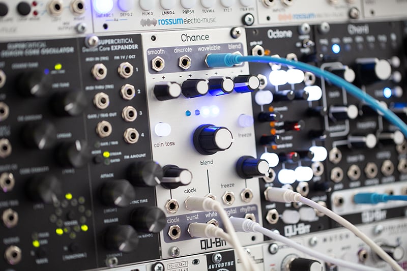
Techniques: Sample and Hold
The classic random source in modular is the sample and hold—this is also often seen on the LFO/modulation section of keyboard synths, such as the SH-101 or the Polivoks (and countless others!). A typical sample and hold provides a clock input (which requires a trigger, gate, clock, or similar signal) and a sample input, which can accept any type of signal. Every time the module receives a clock signal, it looks at the signal at the sample input and takes a snapshot of the current voltage value. It holds that signal level at the output until it receives another clock signal, at which point it looks at the new value from the sample input and holds that voltage level at the output.
The most common type of signal to sample is noise, usually white, which turns the sample and hold into a stepped random voltage generator. Audio noise is a continuous, randomly fluctuating voltage that, unlike oscillators, does not contain any repeating, periodic shapes. As a result, it does not have an apparent pitch when monitored directly. This also makes the perfect core for a random voltage generator: since noise ideally provides an equal balance of all voltages, using it as the data input for a sample and hold yields a new completely unpredictable value each time a clock is received.
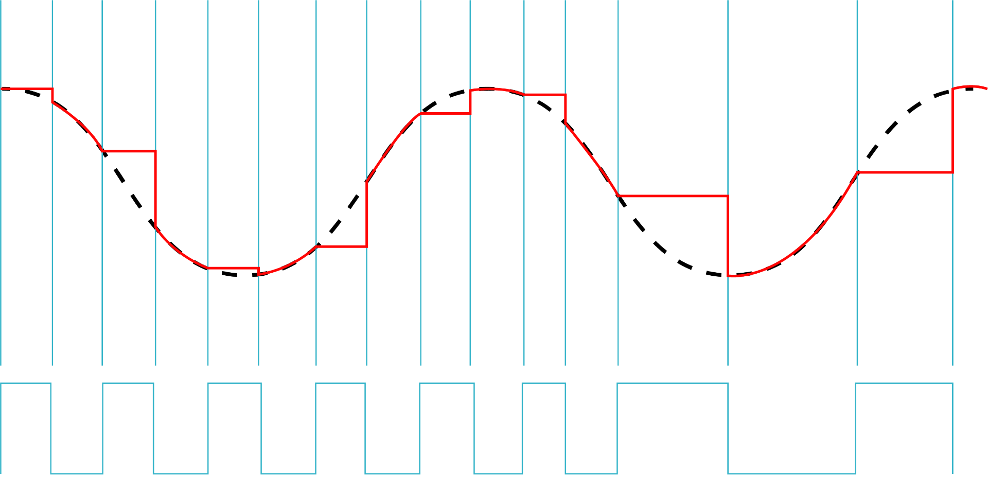
But you are not just limited to sampling white noise—any signal can be used as a sample source. The diagram below illustrates a sine wave running into a sample and hold's data input; the blue lines represent a pulse running into the clock input. The red line is the sample and hold output: a staircase waveshape that follows the contour of the sine wave with a horizontal resolution determined by the clock rate (the sampling rate).
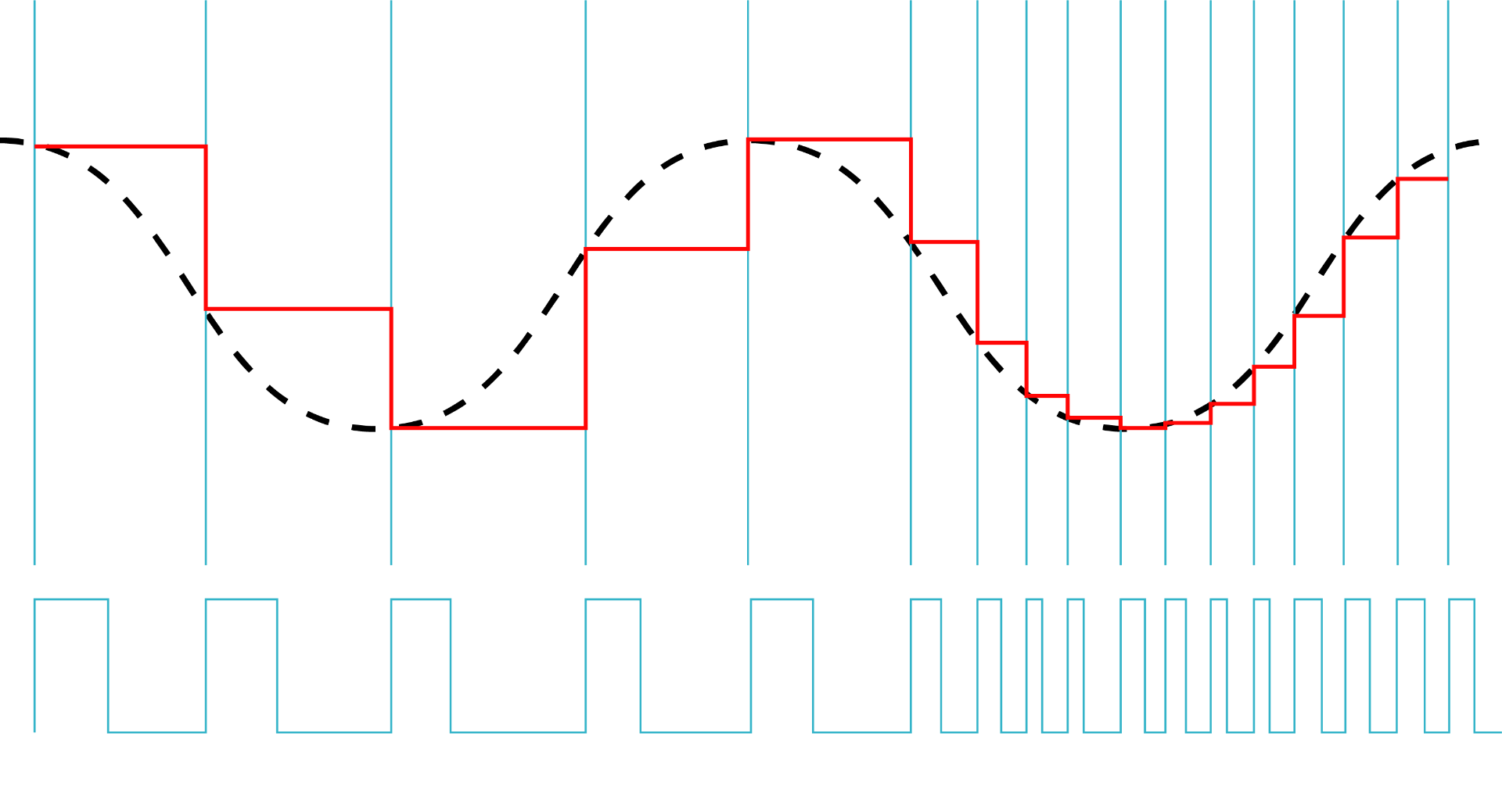
The relationship between the frequency of the input signal and the speed of the sampling clock creates different results. A faster clock speed will result in more samples per second and higher resolution. An LFO, then, can be used to create a staircased, arpeggio-style series of values that roughly follows the LFO shape but whose resolution and pattern is determined by the sample clock speed. Changing the sampling clock speed, LFO speed, or LFO waveform will result in a new pattern.
Other Common Sample & Hold Techniques
Audio rate signals, not just limited to oscillators, can be sampled to add unique harmonic distortion to them, with a resolution set by the clock speed. In this way, a sample and hold can act as a pseudo-bitcrusher or sample rate reducer. The faster the sampling clock, the more closely the output will match the input signal.
This can be illustrated with the sine wave/sample & hold diagram above—and it's closely related to how digital audio works. The rate of the pulse is the sample rate...and messing with this yields artifacts similar to drastic downsampling in software. There are lots of cool tricks hiding there: for instance, you could offset the clock frequency to a fixed ratio above the sampled waveform, creating downsampling effects that maintain a clear harmonic structure. Or, as in the audio example above, you can use it to create brutal, grinding distortion tones.
Often the sample and hold module will be paired with a slew generator. Slew, glide, portamento, or glissando, whatever you want to call it, is a sliding effects between values. So the time it takes to change from one note to the other is controlled by the slew rate, with longer slews taking longer to slide between values. Slew, however, is not limited to adding a sliding effect to pitch but can also be employed in any context you want. For example, the position within an audio sample found in a granular module can be smoothly scrubbed through using a slewed random source.
Techniques: Track and Hold
A track and hold circuit is kind of the opposite of a sample and hold. Like a sample and hold, a track and hold also has a signal input and a clock input. However, rather than only producing stepped signals, the track and hold lets all voltages pass through directly except when it receives a high gate signal, which then freezes it at that voltage level. The diagram below shows a sine wave patched into a track and hold. The blue line indicates the gate patched into the hold input, and the red indicates the track and hold output. Unlike sample and hold, the gate width affects the output. As you can see, it takes this simple waveform and turns it into a more complex one. It can effectively "freeze" a signal, interrupting it and creating interest and in some cases, unpredictability. It can be used in conjunction with other random elements of a patch to add new depth and character.
Using a button or other tactile interface, a modulation source can be held dormant for as long as you want by holding down the button and taking its gate output to the track and hold. Releasing the button will cause the modulation to be active, and pressing it will freeze the modulation again. For example, this could be used to bring in and out a sample and hold's modulation signal of an oscillator. If you have a way to invert the gate signal, it can be used in reverse, only letting through values when you hold the button.
A track and hold can also be used as a sample and hold with a wide enough gate signal. If the track and hold is always holding except for a small window, then it essentially functions as a sample and hold. This requires fine tuning of the hold gate signal on a module with variable gate width. One example of this is the end of rise output on a function generator. With the rise portion of the function generator at its lowest settings, the end of rise gate will almost always be high, providing only a small window with which the track and hold lets voltage through. The implications here are pretty cool—technically a track and hold can perform identically to a sample and hold...but it can also permit continuous signals to pass, allowing a higher degree of nuance than the average sample and hold.
Techniques: Shift Registers
Another way to create random voltages is a shift register. A shift register has two inputs: a clock input and a data input. It’s a little bit like a sample and hold, but only uses binary states (on or off). When the shift register receives a clock input, it looks at the data input and, if it is high, it moves a high state into the first stage of the shift register. Additionally, on clock pulses, whatever data is in the first stage moves to the second and the second moves to the third until it reaches the last step. Digital shift registers can be used like a gate delay for the data input. A gate signal can be input at the data input and then delayed a set number of clock intervals using the cascading outputs. For example, the first stage of a shift register can be used to trigger a kick drum sound, while the third stage can trigger a snare sound. This will create a kick/snare pattern with the snare sound delayed two clock pulses from the bass sound, landing on the one and three of the beat.
It is very hard to create “true” randomness in software, as most analog noise sources are derived from transistors or diodes and are not available in software. So to get around this, many programmers use linear feedback shift registers (LFSR) for random number generation. Instead of external signals being used as data inputs, the LFSR feeds back multiple stages, called taps, into the data input and XOR’s them. XOR means the output signal will be active if one or the other inputs are active, but low if neither or both are. The initial state of the stages of the shift register is called a seed, and it determines the successive states of the shift register—and while the resulting pattern from any given seed is entirely predictable, it is complex enough that the result appears random to the (typical) observer.
 This diagram shows a four-stage shift register with external data input that XORs the last stage with the incoming data signal.
The length of the pseudo-random voltage pattern is determined by the number of bits and combination of taps used. For example, a four-bit LFSR has a maximum length of 15 steps in its maximal configuration, i.e. XORing taps three and four. An eight bit shift register has a maximum length of 255 in its maximal configuration. The length of the LFSR is n^2-1, ie one less than the square of the number, as all bits 0 is not a valid state for an LFSR. If all bits are zero, then there is no data to recycle back into shift register. All bits 0 is a valid state for non-LFSR shift registers as the incoming data is not fixed to the existing data in the register. Non-maximal shift register configurations are seen on the Industrial Music Electronics’ Zorlon Cannon.
In order to turn the binary data into random sequences and not just random gates, a digital to analog converter must be used. A digital to analog converter takes digital data, in this case binary and converts it to a continuous analog signal. This can range from ICs specifically designed for digital to analog conversion to a resistor ladder. One of the simplest forms, an R2R DAC uses a resistor ladder with two resistor values, R and 2R. Basically, it uses a resistor value, R (let's say 10k or 10,000 ohms of resistance) and another twice the value, 2R (20k or 20,000 ohms) of the first resistor in order to turn the binary data into discrete values. The position of the bit in the ladder determines its weighting, or how much it influences the total value. Each of the stages of the ladder contributes half as much voltage to the final output as the stage before it. The first stage is called the most significant bit and changes the output the greatest, while the last bit is the least significant bit. This is an easy to implement, lofi, and cheap way to derive a CV output from a set of binary values. Higher quality DACs may be necessary or preferable as the resolution of the shift register increases.
Techniques: Analog Shift Register
An analog shift register is a related concept based on a series of cascading sample and hold circuits, acting like a combination of a sample and hold and shift register. It is referred to as an "analog" shift register because it does not deal exclusively with digital (on/off) signals, as with a traditional shift register; instead, it acts more like a multi-stage sample and hold.
The ASR was originally conceptualized by Barry Schrader and built by Fukushi Kawakami (known as Mr. Fortune) in 1972. Employed by Yamaha and in residence as a researcher at the California Instutite of the Arts, Kawakami worked with Schrader to produce a series of four modules to augment the capabilities of the Buchla systems Schrader was using for composition. One of these modules was the ASR, which was eventually used in works such as Trinity and Lost Atlantis. Serge Tcherepnin, also based at CalArts at this time, was the first to bring the ASR concept to market as something more than a one-off: it is commonly seen in Serge systems to this day.
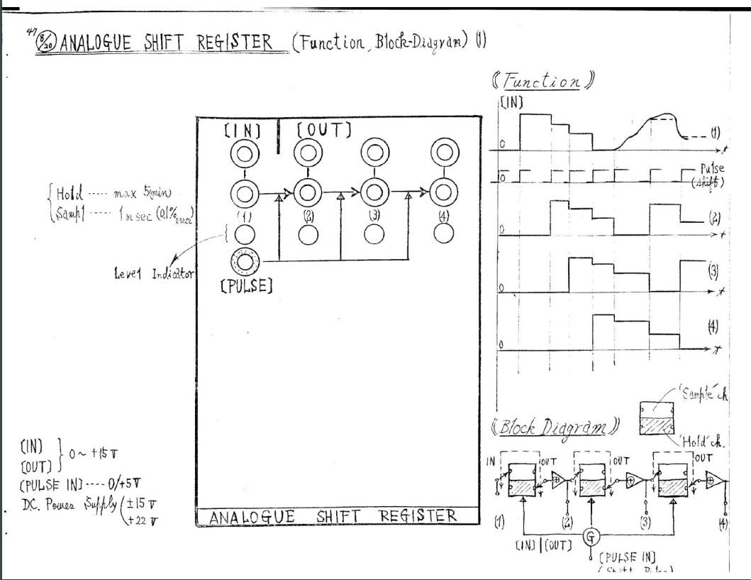 Block diagram of the Schrader/Fortune ASR
When an ASR receives a clock input, it samples the input voltage and puts it into the first stage of the shift register. On successive clock signals, that voltage level is passed to the next output stage, until it reaches the final stage where it is shifted out of the register. When the outputs are patched to the pitch inputs on multiple oscillators, this creates arabesque-like musical results. In visual art, an Arabesque is a visual motif that is copied and slightly offset from each other in space. In a musical sense, these copies are offset from each other in time. Doug Lynner, a long-time user of Serge systems, uses the ASR and arabesque techniques extensively in his music, creating cascading, delay-like patterns between several otherwise independent voices.
These are some of the most common methods of generating randomness in a synthesizer setting, all of which have persisted from the very earliest years of analog synthesis. The next article covers some more specific modules that are used to generate randomness, exploring some of the most interesting ways that this technique has manifested across 50 plus years of electronic instrument design.