What is Logic and Why Do We Care?
If you work exclusively with keyboard or desktop synthesizers, or if you primarily work with DAWs, it's very possible that you've never had to deal with "logic" in the context of synthesis. Modular synthesizers, however, provide access to low-level electronic functions which sometimes do not have an immediately apparent musical purpose—functions that can be combined with other synthesis tools and with one another to extend the functionality of your other devices or to create new means of sound generation, processing, and control. "Logic" in a modular synthesizer is one such set of tools.
There are several different types of logic common in modular synthesizers. It can be used to combine different types of signals and derive now ones. Although it may seem daunting, logic is fairly straight-forward and has a wide variety of applications—and while you won't necessarily find these functions in every modular synth, they can be a great way to extend the functionality of your other modules. Let's dive in and explore some logic.
Boolean Logic
Digital or Boolean logic is the most basic, fundamental form of logic, dealing with binary states: on or off. These can be thought of in traditional synthesizer terms as gate signals. When you press a key on a keyboard its gate output enters a high state (which is sometimes referred to as 1), and when you release it, it goes back to a low state (sometimes referred to as 0). The simplest kind of Boolean logic is a one input logic gate, called a NOT gate. Its output is high if the input is low and low if the input is high. There are also two-input Boolean logic modules that come in a few flavors: OR, NOR, XOR, XNOR, AND, and NAND.
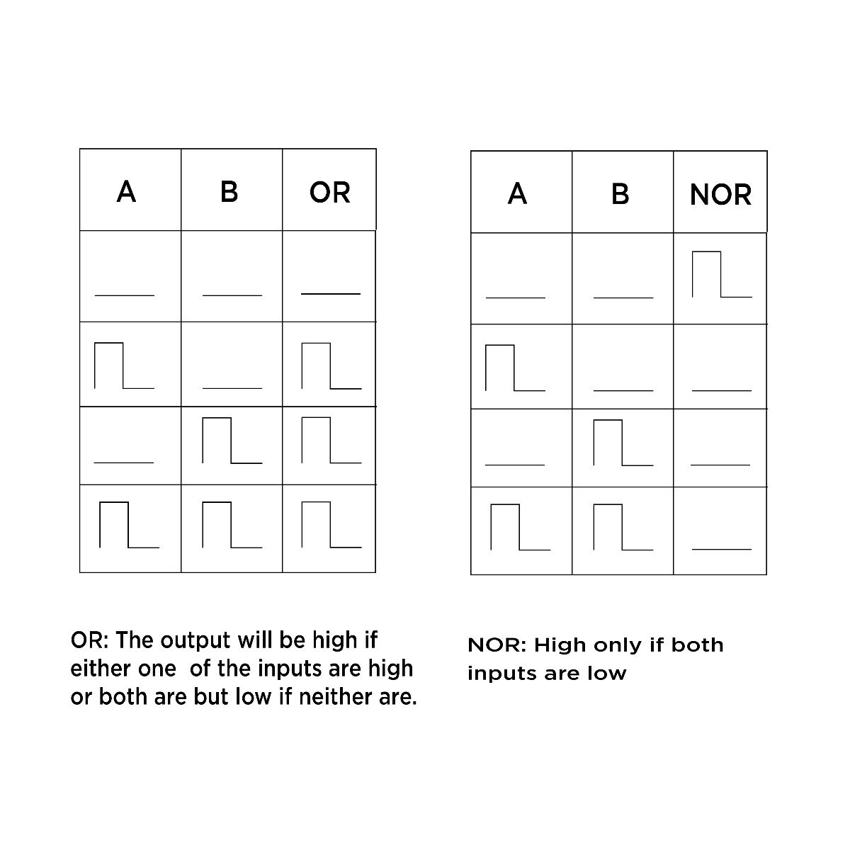
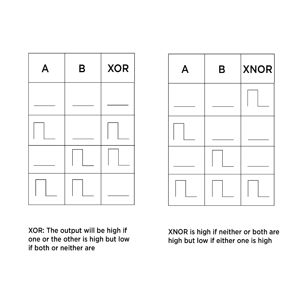
OR: The output will be high if either one of the inputs are high or both are but low if neither are. NOR: High only if both inputs are low and is the logic inverse of OR. Conversely, with XOR, the output will be high if one or the other is high but low if both or neither are. XNOR is high if neither or both are high but low if either one is high, it is the logical inverse of XOR.

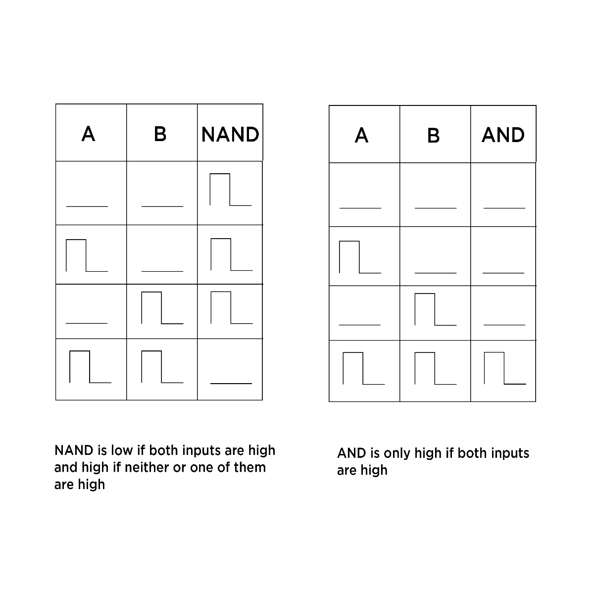
AND is only high if both inputs are high. NAND is low if both inputs are high and high if neither or one of them are high and is the logic inverse of AND.
AND logic can also be achieved using a VCA. Patch square waves to the input and CV input of a VCA and turn down the bias if available. The output will only be high when both the input signal and the CV signal are high. NAND and NOR gates have the property of functional completeness. This means any other logic function can be created by using only NAND or NOR gates.
Boolean logic is often used in conjunction with signals from a clock divider or multiplier. By using different combinations of clocks, complex gate sequences can be achieved. This is useful for programming drum patterns from simple building blocks. To the left is a chart comparing the different two-input logic types with two varying gate patterns to show the related behavior. The audio example shows how different logic types behave when using a divide by 3 and divide by 4 clock signals of a master clock from a clock divider.
Audio rate signals can also be processed by Boolean logic modules. This turns the input oscillators into pulse waves, and provides timbral animation. XOR logic is functionally similar to a ring modulator. Different logic types impart different sounds to different waves at different frequencies. If you have a logic module that has the option to switch logic functions on the fly you can easily hear the differences between different logic types. The audio example demostrates audio rate signals fed into a logic module. The waveshapes, frequencies, and logic types are all altered to show the range of tones.
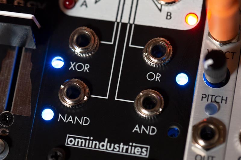
Boolean Logic Modules
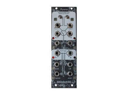
 omiindustriies Illyana Dual Boolean Logic 8hp$250.00Backorder Reserve your order today!
Out of Stock
We're awaiting our next batch of this item. Pre-order to reserve your place in line and we'll fulfill your order as soon as we receive our shipment-
-
Comparators
A comparator takes an input voltage and compares it with a reference voltage. If the input is higher than the reference voltage, the output of the comparator goes high. Often modules that take gate inputs have a preset voltage threshold that an input signal must be higher than to trigger the function. Common voltage threshold levels are 5v, 1v, and 0.5v.
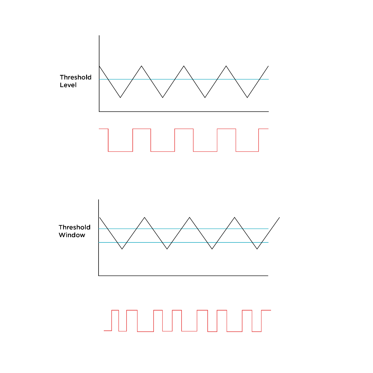 Input (top) and ouput (bottom) from a typical and windowed comparator
Some comparators have the option to CV control the threshold level, which opens up a new world of possibilities. A windowed comparator has a voltage window, an upper and lower threshold setting. The goes high when the voltage appears in this window but is low if the input voltage is higher or lower.
The (now-discontinued) ARC Artificial Neural Network provides many basic logic functions in a single module. It is a patch-programmable logic module, meaning that it uses comparators and boolean logic to create more complex logic functions. Patch programming changes the function of a module by patching the module into itself, an idea which originated from Serge modules. The ANN includes Boolean logic neuron, threshold logic neuron, dual schmitt trigger, two input comparator, and dual NOT gate. But what does all this mean?
ANN's Boolean logic neuron is a two-input AND/NAND gate with inhibit input. The inhibit cancels out the two inputs, making the NAND output high as long as the inhibit input is high. The threshold logic neuron is a three input model of a neuron that performs logic functions. In a biological Neuron, information received by synapses is weighted by the dendrite and summed in the soma, and pulses are fired by the axon. The three inputs each have a weight control, which sets the level of the input voltage. The input voltage level must cross a threshold activation value, set by a comparator. By using different input and threshold levels, different one, two, or three input logic functions are possible. A schmitt trigger uses a windowed comparator with upper and lower thresholds. When a signal crosses the upper threshold, in this case 2.6v the output is held high until the voltage level passes below the lower threshold, in this case 2.1v. The two input comparator has no manual control of threshold. It simply takes two signals at its inputs and compares them, outputting a signal when the + input is higher than the - input. With no signal patched into the - input, the comparator threshold level is normalized to +5v.
Comparators are commonly employed in envelope follower modules. Envelope followers generate continuous control voltages based on the loudness of incoming signals, allowing you to use the dynamic profile of a sound to control any musical parameter you like—commonly employed for "dynamic wah" and volume ducking effects. By running an envelope follower's output through a comparator, you can use incoming audio to generate gate signals, allowing you to trigger different sounds or behaviors based on the presence of other sounds. Such a feature can be found in the Doepfer A-119, Xaoc Devices Sewastopol, and in dramatic extremes with the ADDAC System 401 Gated Envelope Follower.
Modules with Comparators
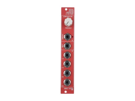
- ADDAC System ADDAC208 Comparator & Rectifiers 4hp
- Sale
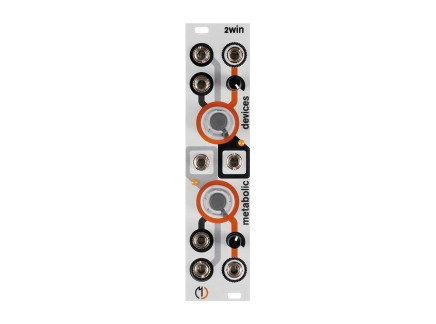
$135.00 $110.00In Stock Available immediately! - Metabolic Devices 2win Dual Window Comparator 6hp$155.00Backorder Reserve your order today!
Out of Stock
We're awaiting our next batch of this item. Pre-order to reserve your place in line and we'll fulfill your order as soon as we receive our shipment - Random Source Serge Divide by N Comparator (NCOM) 10hp$269.99Backorder Reserve your order today!
Out of Stock
We're awaiting our next batch of this item. Pre-order to reserve your place in line and we'll fulfill your order as soon as we receive our shipment

Analog Logic
Analog logic involves mathematical combinations of continuous voltages. Boolean logic deals with binary states, on or off, while analog logic has to do with mathematics based on continuous voltage levels. Sum is voltage addition, just adding the two voltages together, which can be done with a mixer. A NOT function can be achieved with an attenuverter and offset, inverting the signal. Some analog logic functions share their names with Boolean logic types but they differ in their exact implementations. Analog AND (sometimes referred to as minimum) outputs the lowest input voltage. Analog OR (maximum) outputs whichever input voltage input is higher. These two functions can be seen on the Serge module Peak and Trough.
The Mystic Circuits Ana is an analog logic module, that includes four inputs and six outputs. The outputs include min (AND) and max (OR), which we've already touched on. The VCA is a four-quadrant multiplier, which can be thought of as a bi-polar VCA or analog XOR. The mag is the difference between the two inputs, so if one input was at 5v and the other was at 3v, the difference would be 2v. The step is a track and hold function, and box is a bipolar comparator that results in a three-level square wave. By patching into the In 1 or 2, the knobs act as attenuverters. By patching into the Sum 1 or 2, the knob acts as an offset. Patching into both will first attenuvert the signal input and add it to the sum input at its original level. With nothing patched into the inputs of either channel, the knob will act as a static DC offset. This module packs a lot of functionality in a small package and even small adjustments to the knobs result in complex and interrelated changes that can go to a variety of different destinations. It can also be used with audio rate signals for gnarly distortion tones.
Sequential Switches
Switches in a synthesizer can be a useful way of routing signals to multiple locations. They can be used to mute signals, to switch audio sources, to send signals to one of many destinations—there are tons of applications! The simplest switches are only mechanically operated, but many Eurorack modules (such as the WMD SL3KT) allow for dynamic switching between multiple signals.
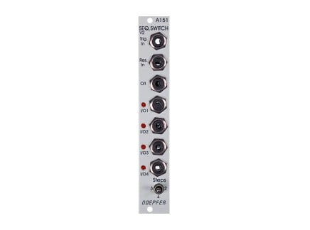
Sequential switches, a type of multiplexers, have one jack that can be used as an input or output and multiple jacks that provide the opposite function. So you could have for example one input and four outputs or four inputs and one output. Switches include a means of addressing which channel is active at any given time. For sequential switches, this is typically done linearly with a clock source or using binary—but some switches also allow for CV addressing (using a control voltage to select the active channel). So you could run multiple CV sequences into the sequential switch and then cycle through them using a clock signal. This is commonly done, for instance, to extend the length of short multi track sequences. By running the three channels out of a Make Noise Pressure Points + Brains into three inputs of a sequential switch and switching the active channel with Pressure Points's first gate output, you can create twelve-step sequences: it will first read the top row, then the middle, and then the bottom in order. Try this out with a Doepfer A-151 set to three step mode.
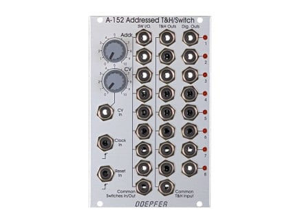
In voltage addressed switches, different voltage levels correspond to different channels. This can be seen on the Doepfer A-152 Addressed T&H/Switch. It has an eight-channel multiplexer with common switch input/output. The stages active can be selected by CV with both and offset and attenuator, or via clock with both clock and reset inputs. Changing the CV level will select different switch stages, while the clock input linearly steps through the stages. When using both the clock signals and CV input, the CV input has the highest priority and will override the clock information. A-152 also features a common track and hold input with eight outputs. When a stage is active, it will let the signal preset pass unaffected until the next active stage is selected, at which point the T&H output freezes at the current voltage level and passes its value to the next stage. Finally, the digital output section, something like a chain of windowed comparators, has eight gate outputs. Gate outputs are selected based on the incoming CV and clocks: when one stage is active, its corresponding gate output is high, all others are low. This can be used to trigger envelope generators or it can be used to shorten the sequence from eight steps using the reset input.
Illyana from omiindustriies features a programmable logic section that has a two-bit binary based sequential switch. It allows you to select which one of the four logic types are available at the X and Y outputs. The program switches and gate inputs are XOR'd with each other, so if the switch is in the high position (1), a gate input will effectively cancel it out.
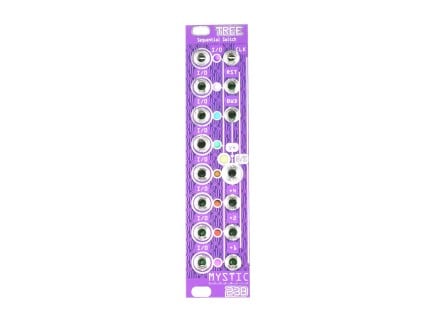
The Mystic Circuits Tree is a sequential switch that includes both clock based sequencing and binary addressing of channels. The three binary inputs address which of the eight I/O's are active. The first input is the 1's column, second is 2, and the third is 4. The active stages go from zero (000 or all stage low) to seven (111 or all stages high). So for instance to address the sixth place, you would send gates to the second and third binary inputs, 4+2=6 (110).
As seen in the video above, sequential switches can be used to provide evolving melodies and rhythms (in this case, with the ALM Boss Bow Tie). For example, different sequences could be patched into different inputs on a sequential switch and then switched between to create new sequences. This could take simple eight step sequences and turn them into something altogether new, particularly if you irregularly jump between sequences. Or you could take combinations of sound sources that vary in timbre and pitch, as related or unrelated as you want, and select between them to create beats or melodies.
Interesting Sequential Switches
- Doepfer A-151 Quad Sequential Switch 4hpAs low as $73.00Multiple Options Make a selection for stock info
- Mystic Circuits Tree Sequential Switch 6hp$250.00Backorder Reserve your order today!
Out of Stock
We're awaiting our next batch of this item. Pre-order to reserve your place in line and we'll fulfill your order as soon as we receive our shipment -
Make Noise Maths, The Ultimate Logic Machine
I would be remiss if I did not mention the functionality of the most famous of Eurorack modules, the Make Noise Maths. It takes direct inspiration from the Serge Dual Universal Slope Generator, a cornerstone of the Serge modular system. Like many Serge modules, it has the ability to be patch programmed. It builds on the DUSG design of Serge and adds attenuverters and a mixer that can be used to expand the patch programming possibilities. The dotted blue lines in the diagrams indicate patch programming connections within Maths. Although it is often relegated to the task of envelopes or LFOs, it can do so much more. Obviously, as noted at the bottom of the panel, it can handle analog OR logic, and signals can be added or subtracted using the mixer and attenuverter sections, but let's explore some of the other things Maths can do.
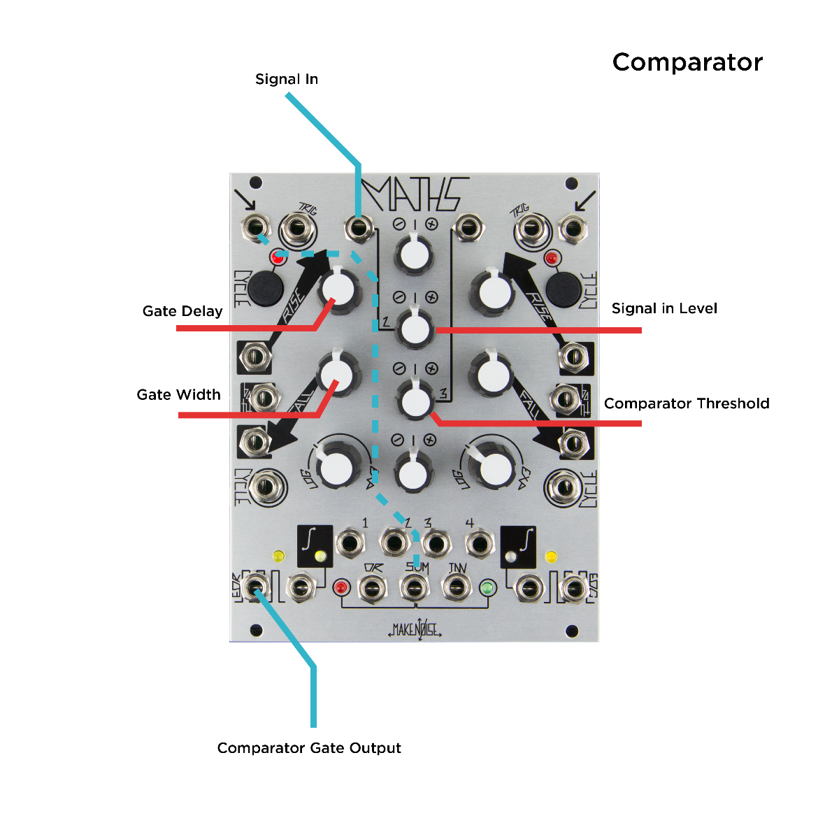
Maths can act as a comparator. As seen in the images above, a simple comparator can be achieved using a signal patched into channel 2. The channel 2 attenuverter acts as the input level, and channel three acts as the threshold level. Take the sum output and patch it into the signal input of channel 1. The rise control acts as a gate delay, and the fall control sets the gate width.
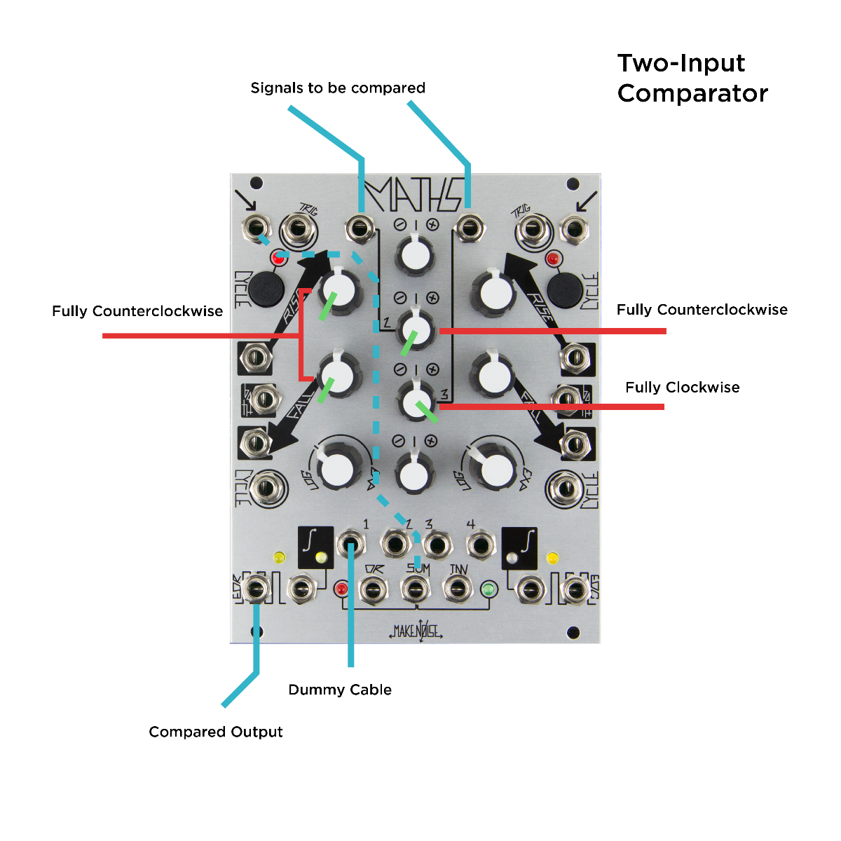
Or, as in the second image above, two signals can be compared by patching into channels 2 and 3. Set channel 2 attenuverter to fully counterclockwise and channel 3 to fully clockwise. Take the Sum output and patch into channel four signal input and patch a dummy cable into the channel 1 variable output, muting it from the sum output. The end of rise gate output will go high when the signal present at channel 3 is higher than the signal present at channel 2. The rise and fall settings should be set at fully counterclockwise or else the output may behave in unexpected ways (which may be useful in certain scenarios). Play around with it!
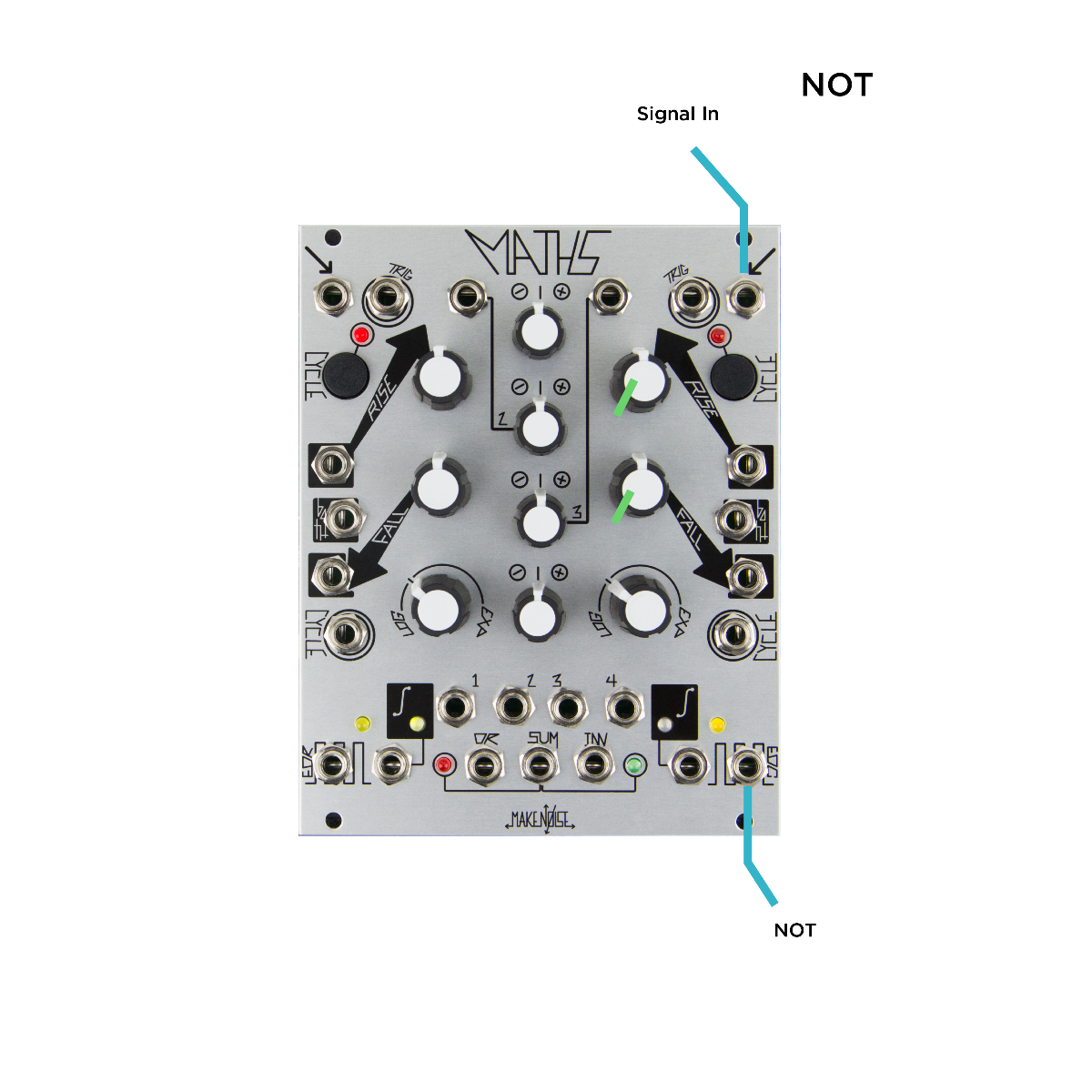
The basic types of Boolean logic are also possible using Maths, as seen in the images below. Maths channel 4 end of rise gate output can act as a NOT gate, inverting the state of the signal present at the input. The end of rise is high with no signal present at the input and goes low when one is present. By default, the rise and fall controls of channels one and four should be set all the way counterclockwise, but playing with these controls can add gate delay to your logic patch (like in the one input comparator example), which you may find useful.
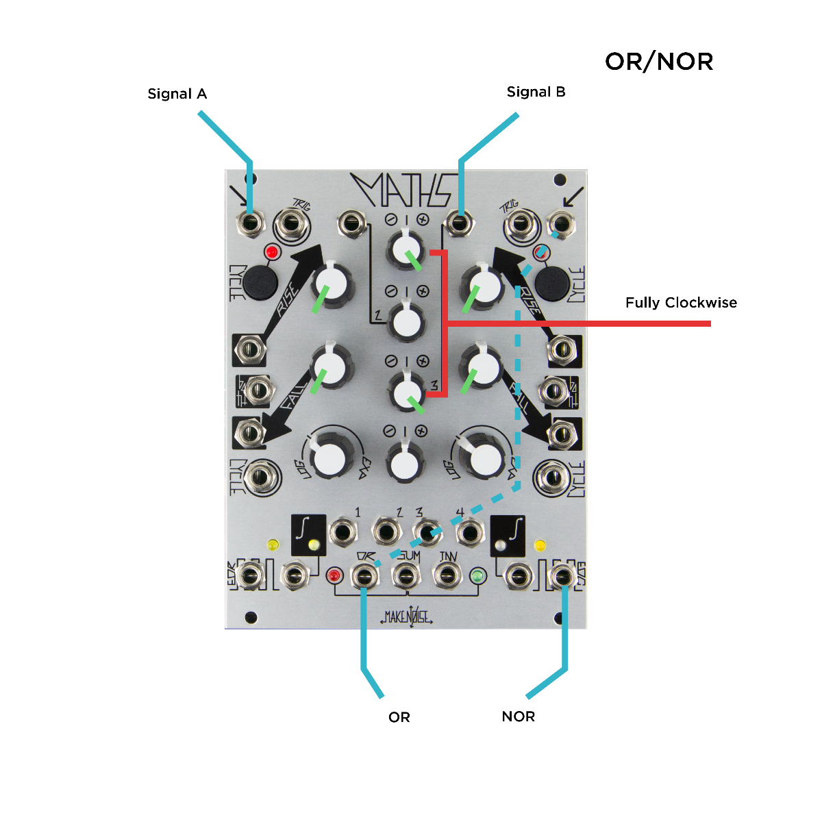
You can derive the complementary logic function of any of these types but taking their output and running them into channel 4 signal input. The NOT function inverts the logic and provides its complementary inverse logic function. For Boolean OR logic, patch gate signals into channel 1 signal in and channel 3 signal in. Take both of the corresponding attenuverters and turn all the way clockwise. The analog OR output will act as a Boolean OR output.
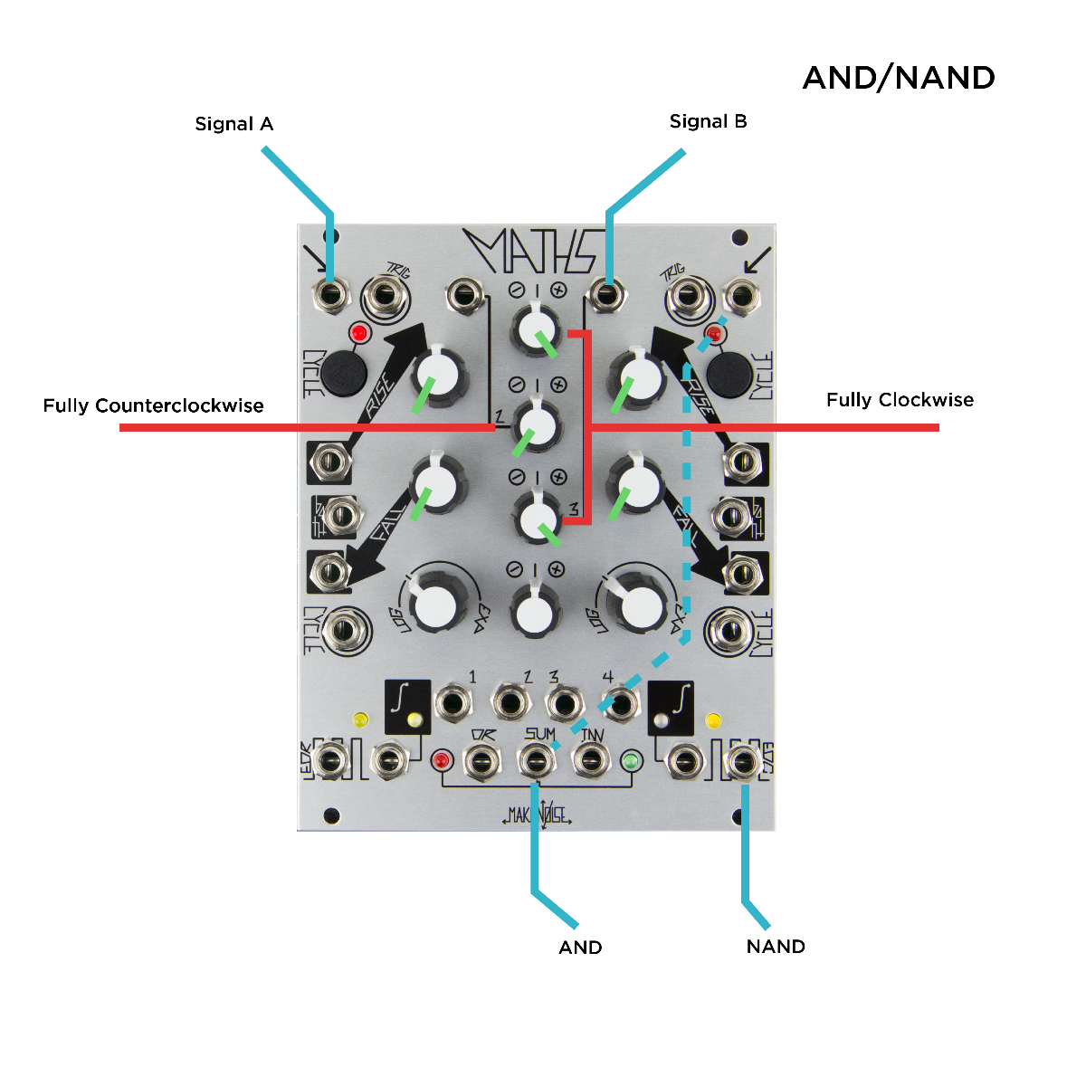
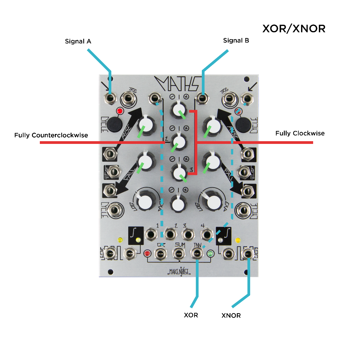
For AND logic, patch gate signals into channel 1 signal in channel 3 signal in. Set the attenuverters of channels 1 and 3 fully clockwise, and the attenuverter of channel 2 fully counterclockwise. The Sum output will only be high if both ch 1 and 3 are high. In order to get XOR logic, patch gates signals into channels 1 and 3 and set fully clockwise, take the analog OR output to CH 2, set fully counterclockwise. Take the inverted Sum output of Maths for XOR logic.
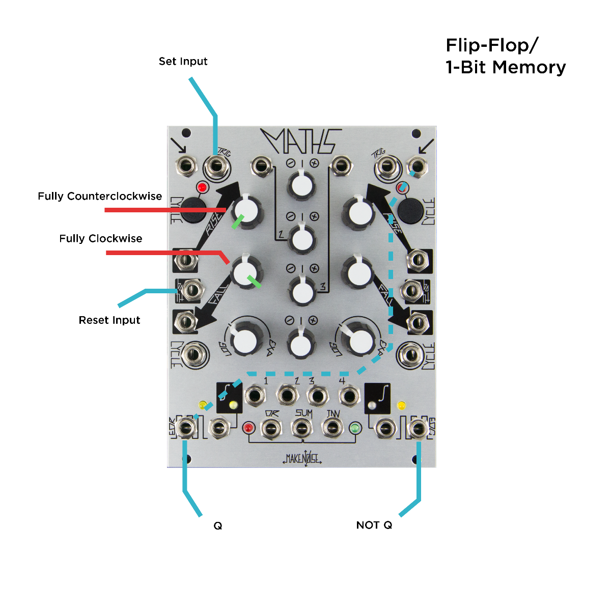
One type of logic we haven't talked about is a flip-flop, which basically acts as a one-bit memory buffer. This can be achieved with Maths in a novel way. Take a gate signal and patch it to the trigger input of channel 1 to set the state of the memory. Set the rise full counterclockwise, fall fully clockwise, and curve to linear. The end of rise gate output stores whatever signal is present at the input. Patching a gate into the Both CV input of channel 1 resets the flip-flop. By taking the channel 1 EOR output and patching it into channel 4 signal input, you can achieve a NOT Q output, which is the opposite of Q. The voltage memory has a time limit of about three minutes.
Of course, feel free to adjust any of the controls on these patches—the knob setting instructions are only there to help get you started. Use them as a foundation for more in-depth explorations of the logic functions of Maths.
These are just a few examples of modular logic and their applications. Like most modular synthesizers, exploration is the best way to get familiar with logic functions. Try sending different kinds of signals into logic modules, mixing, matching, and discovering some of the many applications for logic modules.