Simply put, a sequential switch is a special type of signal routing module. Depending on the specific module, it might be used to route a single input signal to many destinations; alternatively, it might be used to select between many potential input signals for a specific, single destination.
Generally speaking, a sequential switch switches between its various inputs (or outputs) depending on when it receives a trigger—advancing to its next input or output each time a trigger is received. So, that's the basic idea; but let’s look more closely at how a sequential switch works.
How Does a Sequential Switch Work?
Here is a quick video demonstrating how a sequential switch works.
In the video above, you'll see a demonstration of a very straightforward patch in the free modular synthesizer software VCV Rack. This patch uses BogAudio’s 8:1 (more on what that means in a bit) sequential switch. The switch has been limited to 2 steps, so that it only cycles between the first two inputs.
Patch at a glance:
- VCO > VCF > Audio Out
- Two Square LFOs > 2 inputs of the sequential switch
- Clock > Clock sync of the two LFOs
- LFO1 is running at the same rate as the clock
- LFO2 is running at twice the speed of the clock
- Clock > Clock input of the sequential switch
- Sequential Switch Output > VCF Cutoff
Every time the switch receives a trigger (or a gate) on its clock input, it moves to the next available input. In our case, we have limited the switch to only 2 inputs using the “Steps” knob. The switch begins at the first input, which is our square LFO1. It stays there until it receives a trigger from the clock. On receiving the trigger, it jumps to the next input, which is input number 2.
It stays on input number 2, which is our square LFO2, until it receives the next trigger. On receiving the trigger, it jumps back to input number 1. And hence, it keeps cycling between the two inputs.
Types of Sequential Switches
Now that we have the basic concept down, we should clarify that there are two kinds of sequential switches:
- Many-to-one sequential switch: As the name suggests, these switches have several inputs and one output. In our example above, the BogAudio sequential switch has 8 inputs and 1 output. Hence, we say it is an 8:1 sequential switch.
- One-to-many sequential switch: These switches have one input and several outputs. They are useful for routing one signal to several destinations, sequentially.
On the difference between a mult and a one-to-many sequential switch: Please note the importance of "sequential" in the name "sequential switch". A signal multiple module (mult) also routes one signal to several destinations. However, a mult makes copies of the original signal and distributes it to several destinations simultaneously. In the case of a one-to-many switch, the switch cycles between its various outputs according to the rate of its clock input. The many outputs go to their destinations in sequence—but only one output from the switch is active at any given time.
Some of Our Favorite Sequential Switches
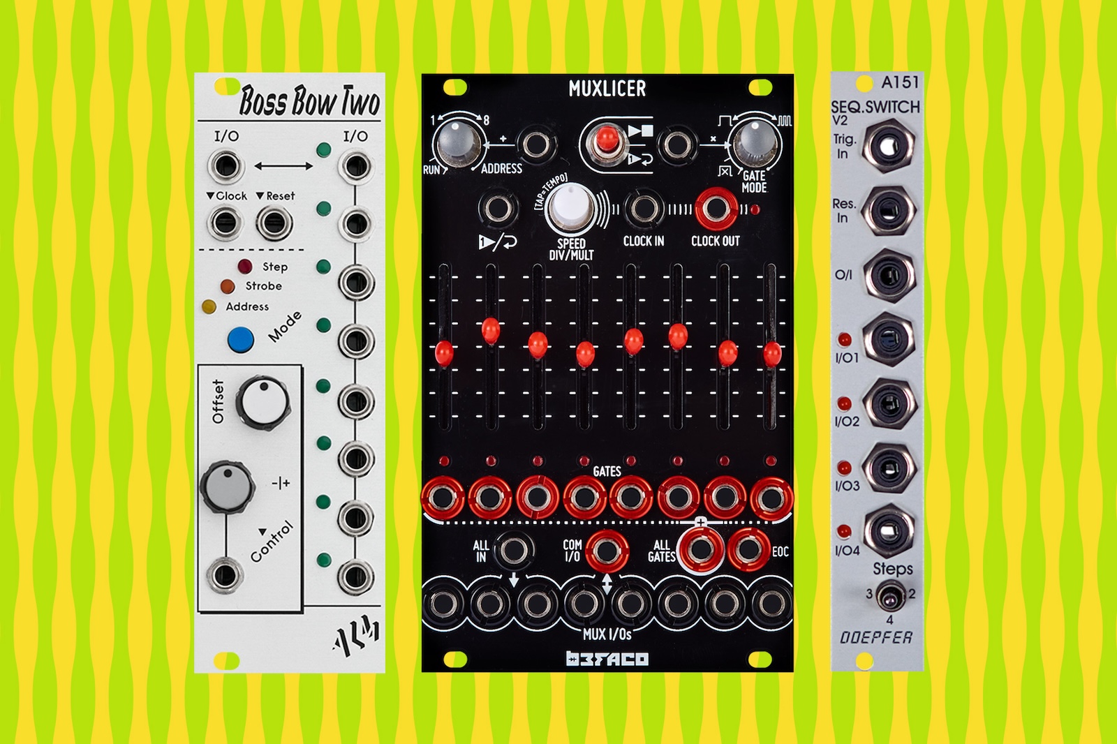
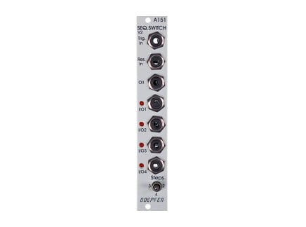 Doepfer A-151 Quad Sequential Switch 4hpAs low as $73.00Multiple Options Make a selection for stock info
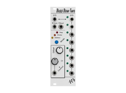 ALM Busy Circuits Boss Bow Two Switch + Signal Router 8hp
- Sale
$199.99 $174.99In Stock Available immediately!
Patch Examples with Sequential Switches
A sequential switch can be an incredibly powerful tool in a modular rack. It can, especially, be useful in live performance scenarios. Here are some patch examples using a sequential switch for you to explore:
1. Building longer sequences
Sequencing a modular rack can be tricky, especially in live settings. Some complex sequencer modules require menu-diving to build longer sequences. More hands-on ones, such as the Make Noise Pressure Points + Brains combo or the 0-Ctrl, can be limiting. You can three eight-step sequences out of those particular modules, at best. So…what if you want a longer sequence?
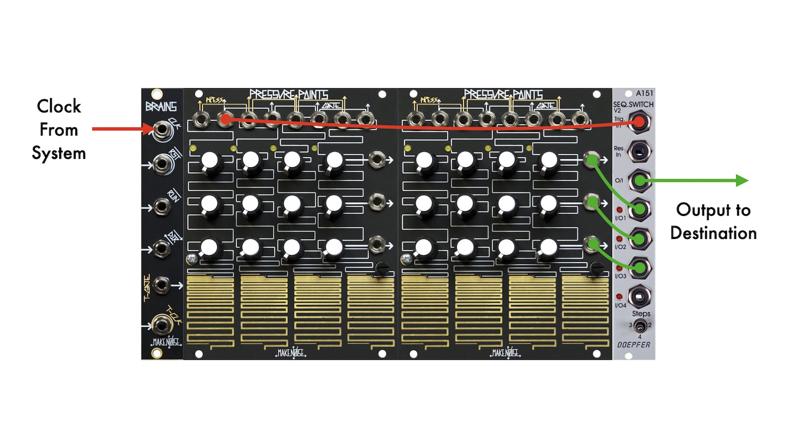
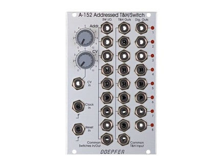
A many-to-one sequential switch, such as Doepfer A-151, can solve that for you. A-151 can be used as a 1:4 or 4:1 switch; but in this example, we'll discuss some of its potential when used as a 4:1 switch. In the case of Pressure Points + Brains, take the three eight-step outputs to the first three inputs of the Doepfer A-151. Patch the first stage's gate output to the trigger input on the A-151. Since each CV sequence of the PP+Brains is eight steps long, we want A-151 to switch between inputs once every cycle—so, we're doing this at the beginning of each cycle through the sequence. Be sure to set the "Steps" switch on the A-151 to the 3 setting.
Once you start clocking PP+Brains from an external source, you'll now have one 24-step long sequence instead of three eight-step long sequences. You can, of course, come up with other durations by changing the Steps setting on the A-151, or by resetting the PP+Brains from some specific step in the sequence.
Patch at a glance:
- Three CV outputs of Pressure Points > 4 inputs of Doepfer A-151
- Patch PP Stage 1 gate output to A-151 trigger input
- Patch an external clock to Brains clock input
- Output of A-151 > 1V/oct input on your oscillator
You can apply this principle using any multi-track/multi-lane sequencer and clock source that you might have. Note, if your sequencer doesn't have per-stage gate outputs, you can also mult your master clock and pass it through a clock divider.
2. Randomizing drum sequences
For this patch, you will need a sequential switch with addressable steps, such as the Befaco Muxlicer. You can supply CV to the “step” function of Muxlicer to determine which input the switch will jump to when it receives a trigger.
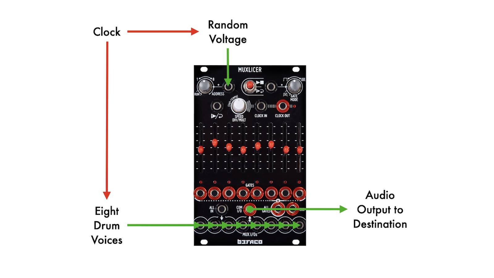
The idea is simple: patch your drum voices into the inputs of Muxlicer. Supply a random CV to the "steps" knob on the top left of Muxlicer. A sample and hold is an obvious choice for randomizing voltages. Take the common out of the Muxlicer and go into your VCA, mixer, or other downstream processing as desired.
Patch at a glance:
- Clock divisions/trigger sequences > Individual drum voices
- Individual drum voice outs - The 8 inputs of Muxlicer
- Noise > Sample and Hold (for random CV)
- Sample and Hold out > Steps knob of Muxlicer
- Common output of Muxlicer > Mixer/VCA
You can play around with this basic idea. For example, if you don’t have 8 individual drum voices, you can mult some of them and take them to different inputs of the Muxlicer. Do it so that you have covered all the 8 inputs. Alternatively, you could leave out some of the inputs. When Muxlicer jumps through these inputs, there will be silences in your groove.
Similarly, you can have a lot of fun with clocks in this patch. For instance, clock Muxlicer independently instead of having a master clock for the entire patch. Likewise, play around with different clock divisions for triggering your sample and hold.
If you are using this patch for a live performance, it can be helpful to first run your sample and hold output through another attenuator before the Muxlicer's address input. That way, you can turn on or turn off the randomization of steps, using it as a progression tool during a performance.
3. Building complex modulation
One of the several ways to build complex waveshapes in Eurorack is by using a many-to-one sequential switch. For this patch example, we will use the Muxlicer again.
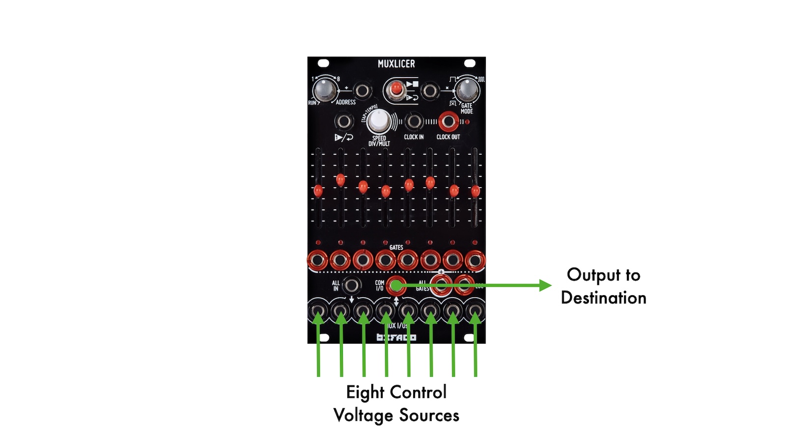
Take different CV sources and route them through the inputs of Muxlicer. Take the common out of the Muxlicer and send the CV to whatever you need to modulate. For example, your filter’s cutoff.
The sliders of the Muxlicer are attenuators for each of the CV signals going into it. As the Muxlicer cycles through its steps, you get different CV values modulating the cutoff of your filter.
Patch at a glance:
- Multiple CV sources (LFOs, Envelopes, Sample and Hold) > Individual inputs of Muxlicer
- Common out of Muxlicer > VCF Cutoff or other destination
- Adjust the sliders on Muxlicer to control the depth of each CV source going into the Muxlicer.
You can also use an ALM Boss Bow Two for creating this patch. Much like Muxlicer, Boss Bow Two is a bi-directional switch with addressable steps and other interesting features.
Patch Ideas for a One-to-Many Sequential Switch
A one-to-many sequential switch is less commonly used than many-to-one switches—but, many switches (including the A-151, Boss Bow Two, and Muxlicer) can operate in both modes. This can be useful in certain scenarios, a few of which are outlined below.
1. Audio Distribution
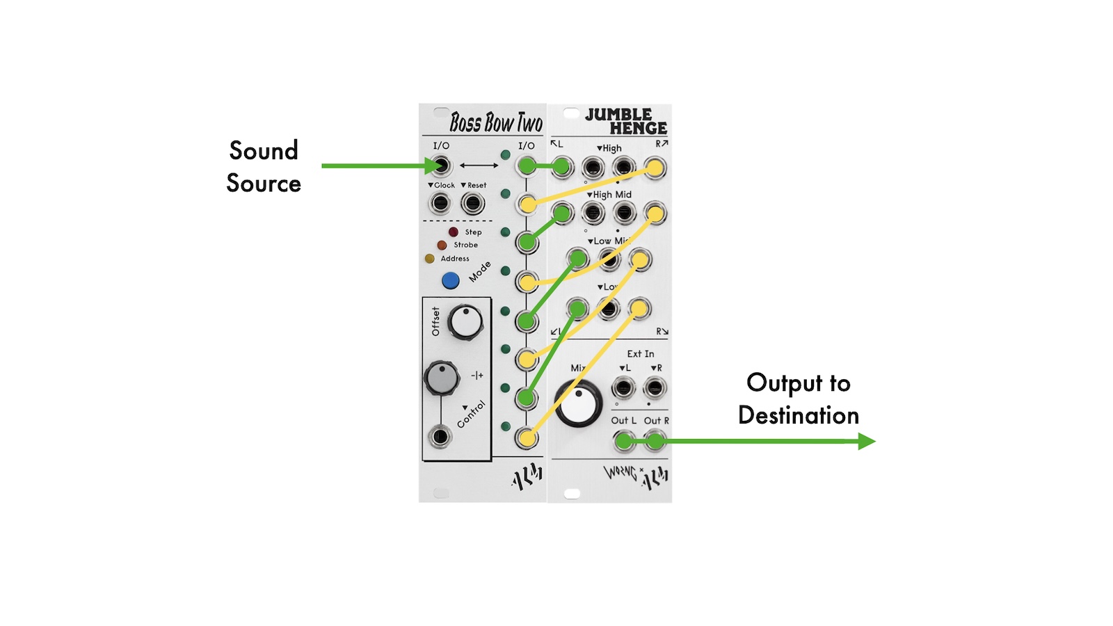
Try sending an audio source to your switch's input. Route each output to a different destination. One interesting patch is to send the outputs into differently-panned inputs on a single mixer, creating jarring, sudden spatial transitions. This patch idea can, for instance, be quite interesting when used with, say, an ALM Boss Bow Two and an ALM Jumble Henge—panning and EQing each output differently from one another.
This patch can also be great with multiple effect processors: try sending your sound source through a switch into many different effects, and then mix all of the effects together for an ever-changing style of processing.
Patch at a glance:
- Sound source > Input of Boss Bow Two
- All Boss Bow Two Outputs > Different Jumble Henge inputs
- Jumble Henge out to your sound system
Note—depending on your patch, you may notice audible clicks when switching inputs.
2. Multi-Voice Animation
Take a common CV source—such as a triggered envelope—and run it through Boss Bow Two. Use the same gate source to both trigger the Boss Bow Two and your envelope. Run the different outputs of Boss Bow Two to the CV inputs of a multi-channel VCA, such an Erogenous Tones VC8 octal VCA. Patch eight different audio sources to the VC8's signal inputs.
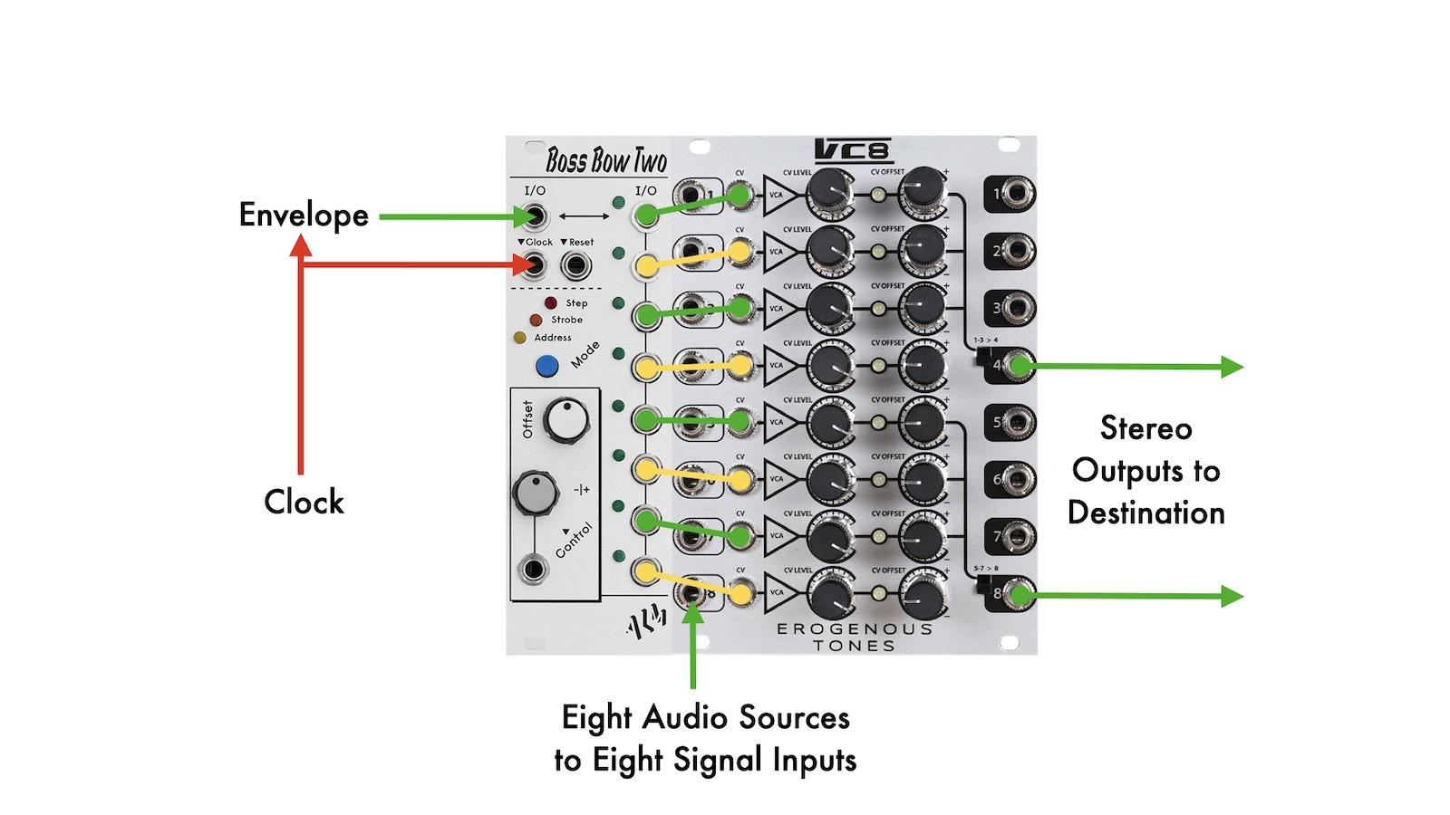
Patch the sum outputs from the VC8 to a mixer. With each incoming gate—be it from a clock, another sequencer, or a manually-triggered voltage source, will route your envelope to the next VCA in the series, creating a gated multi-timbre patch. This is similar to the prior patch, but a bit more nuanced, with control over the amplitude contour of each sound.
Patch at a glance:
- Eight sound sources > VC8 audio inputs
- Clock source > envelope trigger input & Boss Bow Two clock input
- Envelope output > Boss Bow Two input
- Eight Boss Bow Two outputs > VC8 CV inputs
- VC8 sum outputs to mixer
Like before, you can add complexity to this patch by randomizing the addressable CV input on Boss Bow Two.
Other Ideas to Explore with Sequential Switches
You can get really creative with a sequential switch. For example, use the one-to-many CV patch for modulating different parameters of your effects modules. Similarly, run multiple effects through a switch. Move through them sequentially to create some other-worldly soundscapes.
You could also run multiple sample-and-hold outputs through a sequential switch. Each sample and hold could be sampling white noise and being triggered at a different rate. This idea could, especially, be useful for building a generative patch.
If you are looking for a sequential switch to add to your rack, here are some of the best signal routing modules out there.
More Switches to Check Out
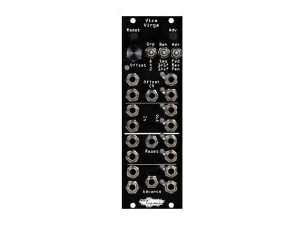
 Noise Engineering Vice Virga 8-Channel Sequential Switch 8hpAs low as $309.00Multiple Options Make a selection for stock info
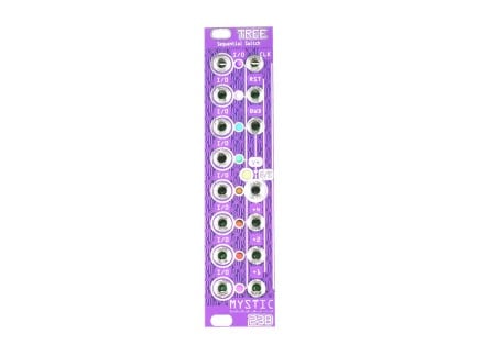
- Mystic Circuits Tree Sequential Switch 6hp$250.00Backorder Reserve your order today!
Out of Stock
We're awaiting our next batch of this item. Pre-order to reserve your place in line and we'll fulfill your order as soon as we receive our shipment -