Cart
Quantity :
Loading...

 Close Menu
Quantity :
Even if you are unfamiliar with the term “frequency modulation,” you might have heard FM synthesis. Frequency modulation is the basis of many classic synthesizer designs, including Yamaha's DX series. That bright, glassy electric piano in countless '80s ballads? That’s FM. The punchy, metallic bass lines in Sega Genesis games? Also FM. Even some of the default ringtones and notification sounds on early cell phones were based on Yamaha FM chips.
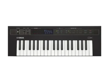
Yamaha’s DX7, released in 1983, helped define the sound of a decade, and its presets made their way into hits by Whitney Houston, Phil Collins, and countless others. FM synthesis became a backbone of video game music in the 16-bit era through iconic soundtracks like Sonic the Hedgehog and Streets of Rage. Even today, FM’s crisp and bell-like resonances resurface in synthwave, vaporwave, and modern electronic music. And FM has never stopped being a defining technique used in hardware synthesis.

What sets FM apart from other classic synthesis techniques such as subtractive synthesis and additive synthesis is its efficiency. Subtractive synthesis starts with harmonically rich waveforms like sawtooths or square waves and then removes frequencies using filters. Additive synthesis builds complex tones by adding together many sine waves. In contrast, FM synthesis creates rich, evolving spectra by modulating one simple waveform with another (or in the case of multi-operator FM, by chaining multiple modulators together in a network). Even with just two oscillators, though—a carrier and a modulator—you can generate a new complex waveform that would otherwise require an entire bank of additive components.
While FM is often associated with digital synths and software plugins, its principles are just as alive in hardware. The concept is simple: route the output of one oscillator into the frequency input of another. In fact, frequency modulation is one of the foundational ideas behind the “West Coast” style of synthesis—pioneered by Don Buchla—which favors wave-shaping and complex modulation over filter-centric designs. In the world of modular synthesis, FM is at the heart of many so-called complex oscillators, where one oscillator modulates another at audio rates, creating swirling, harmonically dense tones without a filter in sight.
In this Part 1 of a two-part series, we’ll start with the foundations: how FM synthesis works, why it produces its signature sidebands, and how complex harmonic spectra can emerge from the simple interaction of simple waves. We’ll also touch on phase modulation here, since frequency and phase modulation are often used interchangeably, a confusion that dates back to the first digital “FM” synthesizers. In Part 2, we’ll explore FM’s branching forms—breaking down the crucial distinction between linear and exponential FM, and exploring how each affects pitch stability and musicality. Finally, we’ll peer into the more exotic corners of the FM menagerie, where through-zero FM flips phase, and we’ll get really gnarly with a discussion of multi-operator FM. Think of this as a field guide to the many-headed beast that is frequency modulation: an exploration of its species, anatomy, and potential.
If you’ve ever turned the dial on an old car stereo or tabletop radio, you’ve probably seen the “AM/FM” switch. That stands for amplitude modulation and frequency modulation—two different ways of encoding sound (and therefore information) onto a radio signal. Amplitude modulation came much earlier. First used for voice transmissions in the early 1900s, AM was a natural extension of telegraphy. In fact, it was a relatively small conceptual leap: where Morse code used discrete on-off patterns to send messages over a wire, AM used continuous waves whose amplitude (or strength) could be varied to carry audio. This made AM both easy to generate and easy to detect with the vacuum tube technology available at the time.
Frequency modulation was developed in the early 1930s by American engineer Edwin Howard Armstrong as a way to transmit clearer, more reliable audio and better overcome the electrical interference that often plagued AM broadcasts.
To understand how both AM and FM work, it helps to break down a few key ideas. First, think of a wave: it has an amplitude (how “tall” the wave is, which correlates in audio to loudness) and a frequency (how fast it cycles, measured in hertz or Hz). These properties are essential not only to sound but also to how we transmit information wirelessly. At the heart of radio transmission is something called a carrier wave—a steady, high-frequency wave that doesn’t carry useful information on its own but acts as a vehicle for information. To send information like music or speech over long distances, a separate signal must “ride” this carrier wave by altering its shape in some way. That’s where modulation comes in.

[Figure 1: An animated comparison of a signal encoded on a carrier wave through AM and FM]
In amplitude modulation, a complex audio signal, such as music or speech, is used to vary the amplitude of a high-frequency carrier wave. The frequency of the carrier stays constant, while all the information in the audio signal (also called the modulating signal) is encoded as changes in the carrier’s amplitude. These fluctuations in height follow the shape of the original audio waveform and can be extracted by the receiver to reconstruct the sound.
The inherent weaknesses of AM broadcasting—its susceptibility to noise and the inefficiency of transmitting a strong, constant-amplitude carrier—led to the development of FM. Unlike AM, FM keeps the amplitude of the carrier wave constant. Instead, it encodes the audio signal by varying the frequency of the wave. As the voltage of the audio signal rises and falls, the carrier wave compresses or stretches: higher voltages bring the wave cycles closer together, and lower voltages space them farther apart. On the receiving end, the radio tuner locks onto the carrier’s base frequency and uses specialized circuits to detect these frequency shifts. By tracking how the frequency deviates over time, the receiver reconstructs the original audio waveform with significantly less sensitivity to noise.
This concept of modulating one wave with another—well established in communications engineering by the mid-20th century—took a surprisingly long time to find its footing in music. Though composers like Karlheinz Stockhausen and instrument designers like Don Buchla were experimenting with audio-rate modulation as early as the 1950s and ’60s, their approaches were largely exploratory, analog, and difficult to reproduce with precision.
That began to change in 1973, when composer and researcher John Chowning, working at Stanford University, published The Synthesis of Complex Audio Spectra by Means of Frequency Modulation. In this landmark paper, Chowning mathematically demonstrated that when one audible-frequency sine wave (the modulator) is used to vary the frequency of another (the carrier), the resulting spectrum contains a predictable array of new frequencies—sidebands—that mimic the richness of acoustic instruments.
But the real breakthrough came when Chowning applied dynamic envelopes to audio-rate frequency modulation. With the right modulation, he discovered that a simple FM patch could reproduce the complex, brassy timbre of a trumpet or trombone. In the early 1970s, no one had convincingly synthesized brass instruments using existing additive or subtractive techniques, especially not with a method that was both expressive and computationally efficient. As Chowning put it in the conclusion to his 1973 paper:
Perhaps the most surprising aspect of the FM technique is that the seemingly limited control imposed by ‘nature’ over the evolution of the individual spectral components proves to be no limitation at all. This suggests that the precise amplitude curves for each frequency component in a complex dynamic spectrum is not nearly as important, perceptually, as the general character of evaluation of the components as a group.
In other words, the ability to precisely control each spectral component turned out to be less important than the shape of the changing sidebands—the way modulation evolved over time. It was this dynamic movement, not static precision, that proved essential to synthesizing complex tones and convincingly emulating natural instruments.
That efficiency turned out to be crucial. Digital synthesizers were just beginning to emerge in the 1970s, and most were hampered by limited processing power. Chowning’s algorithmic approach to FM—capable of generating a full, evolving timbre with only two or three oscillators—offered an elegant solution to a hard technical problem: how to synthesize rich, lifelike sounds in real time on early digital hardware. Chowning’s insights laid the foundation for digital FM synthesis as a practical tool, and eventually led to Yamaha’s licensing and implementation of his technique in the DX7, an early digital keyboard synthesizer released in 1983.
To understand the different types of frequency modulation, it’s helpful to first develop an intuitive grasp of how and why FM produces complex waveforms in the first place. Recall that all pitched sounds—whether from a violin, a voice, or a synthesizer—can be broken down into collections of sine waves. These are the building blocks of sound: smooth, periodic oscillations with a single frequency and no overtones. Additive synthesis takes advantage of this fact by layering sine waves at various frequencies and amplitudes to reconstruct more complex tones. Even familiar waveforms like square, triangle, and sawtooth waves are just specific combinations of sine waves stacked together, each with their own recipe of harmonics.
Now, consider what a sine wave really is: a smooth oscillation traced out by a point moving around the unit circle at a constant speed. As that point moves, its vertical position (the sine of the angle) goes up and down—creating the classic wave shape when “unrolled” over time. (See Figure 2.) This is a useful way to visualize phase: the wave’s shape is just a record of uniform circular motion. The “phase” is just another way to say “how far around the unit circle.”

[Figure 2: A sine wave is the vertical projection of uniform circular motion—unwrapped along the time axis.]
But frequency modulation breaks that uniformity. In an unmodulated sine wave, the point moves around the unit circle at a constant angular velocity—the angle θ increases steadily over time, and the result is a smooth, periodic oscillation. But in FM synthesis, we modulate that angular velocity. The angle no longer increases at a fixed rate; instead, the speed of rotation is continuously pushed and pulled by another signal—the modulator.
This means that sometimes the point on the circle speeds up, sometimes it slows down, depending on the instantaneous value of the modulating waveform. The result is that the sine wave is compressed and stretched in time. What was once a pure, smooth oscillation becomes a warped and shifting waveform—a complex tone with a spectrum that reflects its constantly changing frequency.
From a mathematical standpoint, this fluctuating angular velocity introduces new frequency components into the signal. These are called sidebands—additional frequencies that appear at integer multiples of the modulator frequency, spaced above and below the carrier. If your carrier is at 440 Hz and the modulator is at 100 Hz, you don’t just hear 440 anymore. You get 340, 540, 240, 640, and so on, with each sideband’s presence and strength determined by how deeply the modulation affects the carrier.
In other words, if you push and pull on the rotational speed of the unit circle—modulating it in a cyclic fashion—it creates ripples. And those ripples propagate outward in the frequency domain as sidebands. The waveform ceases to be a single tone and becomes a constellation of sine waves, all clustered around the carrier, orbiting it like spectral satellites. This constellation’s shape—the number of sidebands, their strength, and how they shift with pitch—is determined by two key parameters: the modulation index (defined as the ratio of frequency deviation to the modulator frequency, and representing how far the carrier frequency is being pushed and pulled), and the ratio between carrier and modulator frequencies.

[Plots of the first six Bessel functions, taken from Chowning + Bristow's book, FM Theory & Applications]
To predict how these ripples behave—to know which sidebands will appear and how strong each one will be—Chowning introduced the use of Bessel functions. Developed in the 19th century to solve problems in physics involving circular symmetry, like the vibration of a drumhead or the diffraction of light through a circular aperture, Bessel functions arise naturally when a system exhibits periodic motion with rotational or oscillatory components. Those same mathematical structures appear in FM synthesis: as the modulating signal pushes and pulls the carrier’s frequency. But don’t let the math intimidate you. While Bessel functions help predict the exact spectral fingerprint of an FM patch, you don’t need to understand them to make music with FM. Chowning was a composer by training, and he approached synthesis with the ear of a musician. Chowning’s real insight wasn’t primarily mathematical; it was musical. He showed that dynamic modulation, shaped by envelopes and movement over time, could mimic the complexity and expressiveness of acoustic instruments. The power of FM lies not in calculating every sideband, but in listening to how they evolve as you play.
One of the most musically important aspects of FM synthesis is the relationship between the carrier and modulator frequencies. When these are in whole-number ratios—like 1:1, 2:1, or 3:2—the resulting sidebands tend to reinforce the harmonic series, producing tones that sound consonant and familiar, like bells, flutes, or brass. But when the ratio is non-integer, and especially when the ratio is an irrational number—say, √2 (approximately 1.414) or e (≈ 2.718)—the sidebands fall in inharmonic positions, creating clangorous, metallic textures more reminiscent of bells or gongs. By controlling how the harmonic and inharmonic ingredients in an FM patch evolve over time and under modulation you can shape a sound’s transients and timbre, imitating acoustic instruments or creating entirely new sounds.
While the term "Frequency Modulation" might imply that the carrier's frequency is directly modulated, in many implementations, this is not exactly the case. Even in the most famous manifestation of the technique—in Yamaha's DX-7—it's not so much about directly altering the number that defines an oscillator's frequency: instead, you can use a secondary (modulation) oscillator to impact the principal oscillator's phase.
By altering the carrier’s position within its cycle at each moment, a computer can achieve similar sonic results more reliably and with less computational overhead. Yamaha still marketed the DX7 as an FM synthesizer, prominently using the term “FM digital synthesizer” in product names, manuals, and advertising. Although the underlying implementation was phase modulation, Yamaha leaned on the term “FM” because it was tied to John Chowning’s patented technique and already associated with groundbreaking, expressive digital sounds. This branding choice, combined with the lack of public technical documentation at the time, blurred the distinction between FM and PM for decades—shaping the language of synthesis even as the underlying method had quietly changed. In all fairness, the observable effect of phase modulation at low modulation frequencies and high indices is modulation of the sound's perceived frequency, even if the effect is generated by technically impacting the carrier's phase.
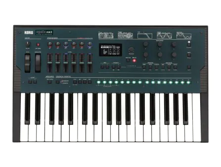
This confusion continues to the present. Instruments like Native Instruments’ Massive (2007) included a phase modulation feature while reassuring users it was “sonically equivalent to the familiar frequency modulation.” Xfer Serum (2014) added a warp mode labeled “FM (From B)” that actually used phase modulation. (Only with Serum 2 did the distinction between FM and PM become explicit.) Marketing copy often conflates the two techniques in ways that manufacturers may not intend. One product description for Arturia’s CZ V states that “CZ V reimagines Casio’s CZ synths […] offering a fresh take on the FM instruments of the ’80s,” associating Casio’s phase distortion with FM nostalgia. Korg’s Opsix (2020) embraced the ambiguity outright by combining PM, FM, and other techniques under the label of “Altered FM.” Tutorials and documentation—from Massive X to Syntorial—continue to refer to FM and PM interchangeably.
To understand the difference, let’s go back to our understanding of a sine wave as a linear representation of uniform rotation on the unit circle. In basic terms, frequency is the rate at which phase changes. (If phase tells you how far around the unit circle a waveform has rotated, frequency tells you how fast it’s spinning.) So when you use one signal to control the frequency of another—as in FM—you’re really changing how quickly the waveform moves through its cycle—that is, its angular velocity around the unit circle.
In digital audio, the computer must calculate the waveform one sample at a time. And while frequency tells you how fast the waveform should be cycling, it doesn’t tell you where it is in the cycle at any given sample. That's what phase tells you. If the frequency is changing from moment to moment, then the amount of phase you move forward by will also keep changing. To figure out the phase at each sample, the computer has to add up all those little frequency changes, one sample at a time. This running total—how far you’ve rotated through the unit circle—is what defines the waveform’s shape. That process of accumulating phase from a changing frequency is a computationally intensive calculation called “integration.”
With digital phase modulation, there is no accumulation, and therefore no integration. Instead of adjusting the “rate of rotation,” the modulating signal directly pushes or pulls the oscillator’s position within its cycle at each moment in time. Imagine skipping ahead or slipping backward on the unit circle (the waveform’s phase), based on the modulator’s instantaneous value. There is no change in angular velocity, and therefore no integration is needed.

[Figure 3: An illustration of phase modulation showing how the phase of a modulating wave (blue) is used to read from a lookup table of carrier values (orange) resulting in a complex waveform (green).]
In practice, when the modulating signal is a pure sine wave and the ratio and depth of modulation is held steady, FM and PM end up sounding the same. That’s because the integral of a sine wave is just another sine wave, shifted in time. So in this special case—sine-versus-sine with constant ratio and depth—FM and PM produce identical spectra. That equivalence doesn't hold in the general case though, where modulation shapes or envelopes vary. However, phase modulation allowed Yamaha to achieve roughly the same expressive sonic results as FM through more technically efficient means. The brassy growls, shimmering bells, and breathy textures that defined the DX7 weren’t the product of strict mathematical fidelity to FM; they were the result of how the sound evolved over time. And in that sense, Yamaha was faithful to Chowning’s key insight, which he has always emphasized in interviews was not primarily a mathematical or computational insight but rather a musical one.
It is important also to note that efficiency isn’t the only reason that FM is often emulated via PM in digital instruments. Unlike analog circuits, digital oscillators operate on tiny time slices (samples) each of which has a discrete value. Without compensating for pitch, if you apply FM to a digital oscillator, you’ll find that the modulation sounds strong and aggressive in the bass, but becomes weaker and thinner as you move up the keyboard. That’s because at higher pitches, each waveform cycle is shorter in time, which means there are fewer samples to spread the modulation across. As a result, the same modulation depth affects the waveform less dramatically in the upper range than it does in the lower range.
Phase modulation sidesteps this issue. In digital FM, the modulator signal is sampled and integrated to produce phase. But that integration is done with fixed-size time steps (samples), and the modulation depth is usually expressed as a fixed number—not dynamically scaled by frequency. So when the carrier frequency increases (e.g., you play a higher note), you get more waveform cycles per second, meaning each cycle has fewer samples. So you're integrating less of the waveform per cycle and consequently the modulation effect gets weaker at higher frequencies. In contrast, PM doesn’t rely on integration, so it applies modulation evenly per sample, regardless of the base pitch of the carrier. This results in a consistent spectral shape across the keyboard.
In the digital world, phase modulation is trivial to implement, because most digital oscillators are already driven by a phase accumulator—a steadily increasing counter that defines the waveform's position over time. Modulation simply involves adding a signal to this phase value before it's passed through a lookup table. Since the phase ramp is precise and predictable, phase modulation comes "for free" in many digital architectures, requiring only a fast enough control rate to preserve modulation detail. In the analog world, however, frequency modulation has long been the standard, while implementing true analog phase modulation poses both theoretical and practical challenges, including the difficulty of cleanly shifting phase in a continuous, voltage-controlled manner.
Given that FM and PM sound so similar, one might wonder why analog PM is even desirable, but there are good reasons why some analog designers pursue this goal. In traditional analog VCOs, manipulating frequency typically means modulating the current charging an integrator, which directly alters the pitch. This method is sensitive to DC offsets in the modulating signal: any constant offset results in a steady frequency shift, introducing pitch errors even when the modulation should be centered. Phase modulation, by contrast, is immune to this problem. Since phase modulation alters the position within the waveform’s cycle rather than its rate of repetition, a DC offset in the modulation signal simply results in a constant phase shift, not a frequency drift. This decoupling of pitch stability from modulation accuracy makes analog phase modulation theoretically very appealing.
But analog circuitry doesn’t give you phase control for free. One simple design concept is to affect phase shifts by crossfading between multiple sinusoids at known phase offsets—such as 0°, 90°, 180°, and 270°. For this to approximate phase modulation however, the circuit would require precise amplitude control and mathematical shaping of the crossfader curve. Simple linear crossfading introduces errors: instead of cleanly shifting phase, it would result in unwanted amplitude modulation.

A particularly elegant, albeit hypothetical, solution to analog phase modulation comes from an unexpected source: the AD639 was a function generator IC designed by analog design pioneer Barrie Gilbert in the 1980s which was intended primarily for scientific instrumentation. It takes a voltage input representing a phase angle (in radians) and outputs precise sine and cosine waveforms, effectively producing a continuously rotating vector on the unit circle. This would seem to make it a near-ideal building block for true voltage-controlled phase modulation, where shifting the input voltage directly rotates the phase without affecting amplitude or frequency.
Internally, the AD639 uses sophisticated analog computation—blending polynomial approximations with multipliers and shaping networks—to deliver accurate, low-distortion trigonometric outputs. But the AD639 is a long-discontinued relic of precision analog computing. And although a discrete implementation of the patent is theoretically possible, it’s unclear whether any current synthesizer design uses a version of the AD639 circuit.
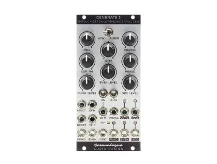
One of the very few commercially-available oscillators that implements true analog phase modulation, the Generate 3 oscillator by Joranalogue, is a Eurorack module that allows for both exponential and linear through-zero frequency modulation (more on that in part 2) as well as phase modulation—even all three simultaneously! Unlike quadrature-based designs, Generate 3’s core is a standard through-zero triangle-core VCO. The key innovation lies in a dedicated waveshaping circuit that directly displaces the waveform’s phase by up to 450 degrees, without relying on dual-phase outputs or interpolation. Separate shaping stages extract the fundamental, even, and odd harmonic components, independent of the phase modulation path. While similar effects can be achieved with external processors, like the Happy Nerding FM Aid (a Eurorack module which, confusingly, is actually based on phase modulation), Generate 3 integrates both the oscillator and phase circuitry in a tightly matched design, offering a high degree of precision that’s more challenging to achieve with separate modules.
In my research for this article, Joran van Gremberghe—the designer behind the Joranalogue brand—confirmed that Generate 3 takes an original and unconventional approach to analog phase modulation:
Generate 3 relies on some fundamental relationships between triangle waveforms and phase. This gives it a very precise 90 degrees of phase displacement per volt of CV, over 900 degrees in total. That allows for very 'deep' PM. The circuit is completely unique, to my knowledge. You can think of it as a very advanced waveshaper. [...] A major distinction between real PM and pseudo-PM is that on Generate 3 you can phase modulate at LFO rates too, and turning the phase knob allows you to 'scroll' through the waveform.
In Part 1 of this guide we covered the fundamentals with a focus on developing an intuitive (rather than than deeply mathematical) understanding of how FM synthesis works, why it creates complex tones, and how we can choose the best type of modulation to achieve our musical goals. We looked at Chowning’s breakthrough, Yamaha’s use of phase modulation in the DX7 and its common confusion with the related technique of phase modulation, and the rare but impressive efforts to implement true analog phase modulation in modules like Joranalogue’s Generate 3.
In Part 2, we’ll take a closer look at the different forms FM can take. We’ll explain linear and exponential FM. We’ll explore through-zero FM and what makes it unique. Finally, we’ll break down multi-operator FM systems, from classic DX7 algorithms to modular reinterpretations.




The information below is required for social login
Sign In
Create New Account